
Sliding spotlight SAR (synthetic aperture radar) as well as implementing method and device thereof

A technology of synthetic aperture radar and sliding beamforming, which is applied in the directions of measurement devices, radio wave reflection/re-radiation, and re-radiation, and can solve problems such as high resolution, imaging distance limitation, and inability to reach

Active Publication Date: 2014-02-12
中科卫星山东科技集团有限公司
View PDF4 Cites 15 Cited by
  • Summary
  • Abstract
  • Description
  • Claims
  • Application Information

AI Technical Summary

Problems solved by technology

[0002] High resolution is an important indicator of SAR. The traditional strip working mode of SAR cannot achieve high resolution due to the limitation of the minimum area of ​​the antenna.
The spotlight mode can achieve high resolution through azimuth scanning, but the imaging distance in azimuth is greatly limited

Method used

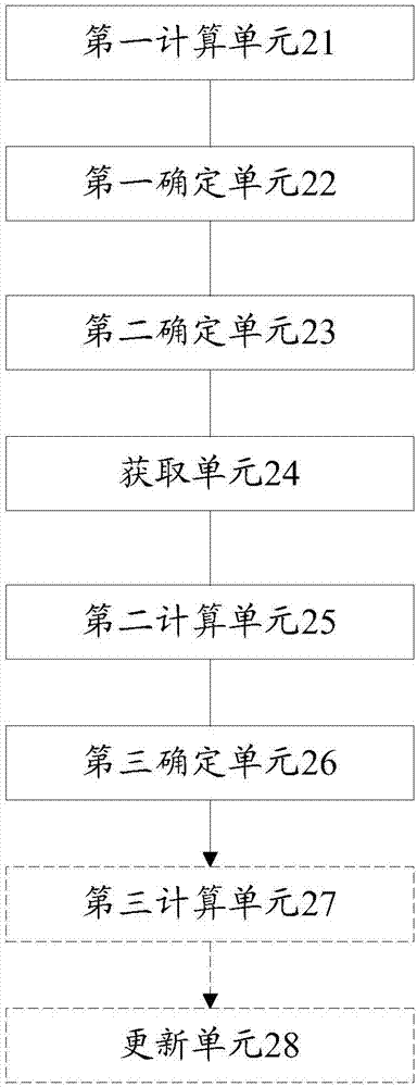

Image

  • Sliding spotlight SAR (synthetic aperture radar) as well as implementing method and device thereof
  • Sliding spotlight SAR (synthetic aperture radar) as well as implementing method and device thereof
  • Sliding spotlight SAR (synthetic aperture radar) as well as implementing method and device thereof

Examples


Embodiment Construction

[0091] In order to understand the characteristics and technical contents of the present invention in more detail, the implementation of the present invention will be described in detail below in conjunction with the accompanying drawings. The attached drawings are only for reference and description, and are not intended to limit the present invention.

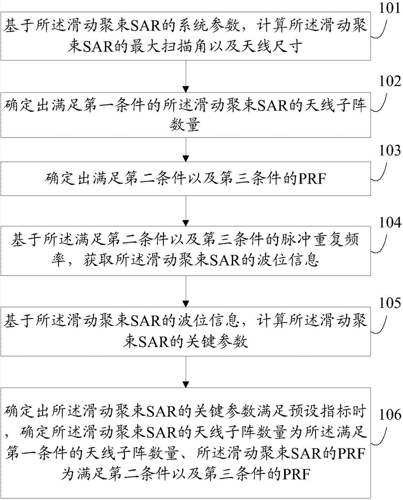
[0092] figure 1 It is a schematic flow chart of the implementation method of the sliding beam spotting SAR according to the embodiment of the present invention, such as figure 1 As shown, the method includes the following steps:

[0093] Step 101: Based on the system parameters of the sliding beam spotting SAR, calculate the maximum scanning angle and antenna size of the sliding beam spotting SAR.

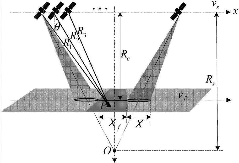
[0094] Specifically, the working principle of spaceborne sliding spotlight SAR is as follows image 3 As shown, the antenna beam always points to the virtual center O, and the closest slant distance from the satellite to the virtu...


PUM


Abstract

The invention discloses a sliding spotlight SAR (synthetic aperture radar) as well as an implementing method and a device thereof. The implementing method of the sliding spotlight SAR comprises steps as follows: the maximum aspect angle and the antenna dimension of the sliding spotlight SAR are calculated on the basis of system parameters of the sliding spotlight SAR; the quantity of antenna subarrays, meeting the requirement of a first condition, of the sliding spotlight SAR is determined; a PRF (pulse repetition frequency) which meets requirements of a second condition and a third condition is determined; wave position information of the sliding spotlight SAR is acquired on the basis of the PRF meeting the requirements of the second condition and the third condition; key parameters of the sliding spotlight SAR are calculated on the basis of the wave position information of the sliding spotlight SAR; and when the key parameters of the sliding spotlight SAR meet the requirements of preset indexes, the quantity of the antenna subarrays of the sliding spotlight SAR is the quantity of the antenna subarrays meeting the requirement of the first condition, and the PRF of the sliding spotlight SAR is the PRF meeting the requirements of the second condition and the third condition. With the adoption of the technical scheme, the key parameters of the sliding spotlight SAR can be effectively designed, so that the sliding spotlight SAR can have higher resolution ratio and larger azimuth width.

Description

technical field [0001] The present invention relates to a sliding beamforming technology in Synthetic Aperture Radar (SAR, Synthetic Aperture Radar), in particular to a sliding beamforming SAR and its implementation method and device. Background technique [0002] High resolution is an important indicator of SAR. The traditional strip working mode of SAR cannot achieve high resolution due to the limitation of the minimum area of ​​the antenna. The spotlight mode can achieve high resolution through azimuth scanning, but the imaging distance in azimuth is greatly limited. The sliding spotlight mode is a combination of the above two working modes. By sliding forward while scanning to achieve high resolution while receiving azimuth width, it is of great significance to the development and application of SAR. [0003] The main design difficulties of sliding spotlight SAR and ordinary SAR lie in the design of antennas with large scanning angles, wave position design and calculati...

Claims


Application Information

Patent Timeline
Patent Type & Authority Applications(China)
IPC IPC(8): G01S13/90
CPCG01S13/12G01S2013/9052G01S13/90G01S13/9052
Inventor 郭磊王宇邓云凯罗秀莲王伟
Owner 中科卫星山东科技集团有限公司
Learn More