Method and apparatus for simultaneous synthetic aperture radar and moving target indication

Inactive Publication Date: 2012-03-08
ANTONIK PAUL +1
View PDF0 Cites 26 Cited by
  • Summary
  • Abstract
  • Description
  • Claims
  • Application Information

AI Technical Summary

Benefits of technology

[0031]Therefore, it is accurate to say that the present invention (1.) can produce synthetic aperture radar and moving target indication at the same time, (2.) can produce strip map and spotlight modes of synthetic aperture radar at

Problems solved by technology

A limitation of the prior art is that synthetic aperture radar requires a small aperture to provide a wide beamwidth to allow long integration times, whereas moving target indication requires large apertures for high gain, narrow beamwidths, and low antenna sidelobes which aid in clutter suppression.
Another limitation of the prior art is that moving target indication implemented using synthetic aperture radar has been constrained to along-track interferometry, and to image change detection, which requires t

Method used


Image

  • Method and apparatus for simultaneous synthetic aperture radar and moving target indication
  • Method and apparatus for simultaneous synthetic aperture radar and moving target indication
  • Method and apparatus for simultaneous synthetic aperture radar and moving target indication

Examples


Embodiment Construction

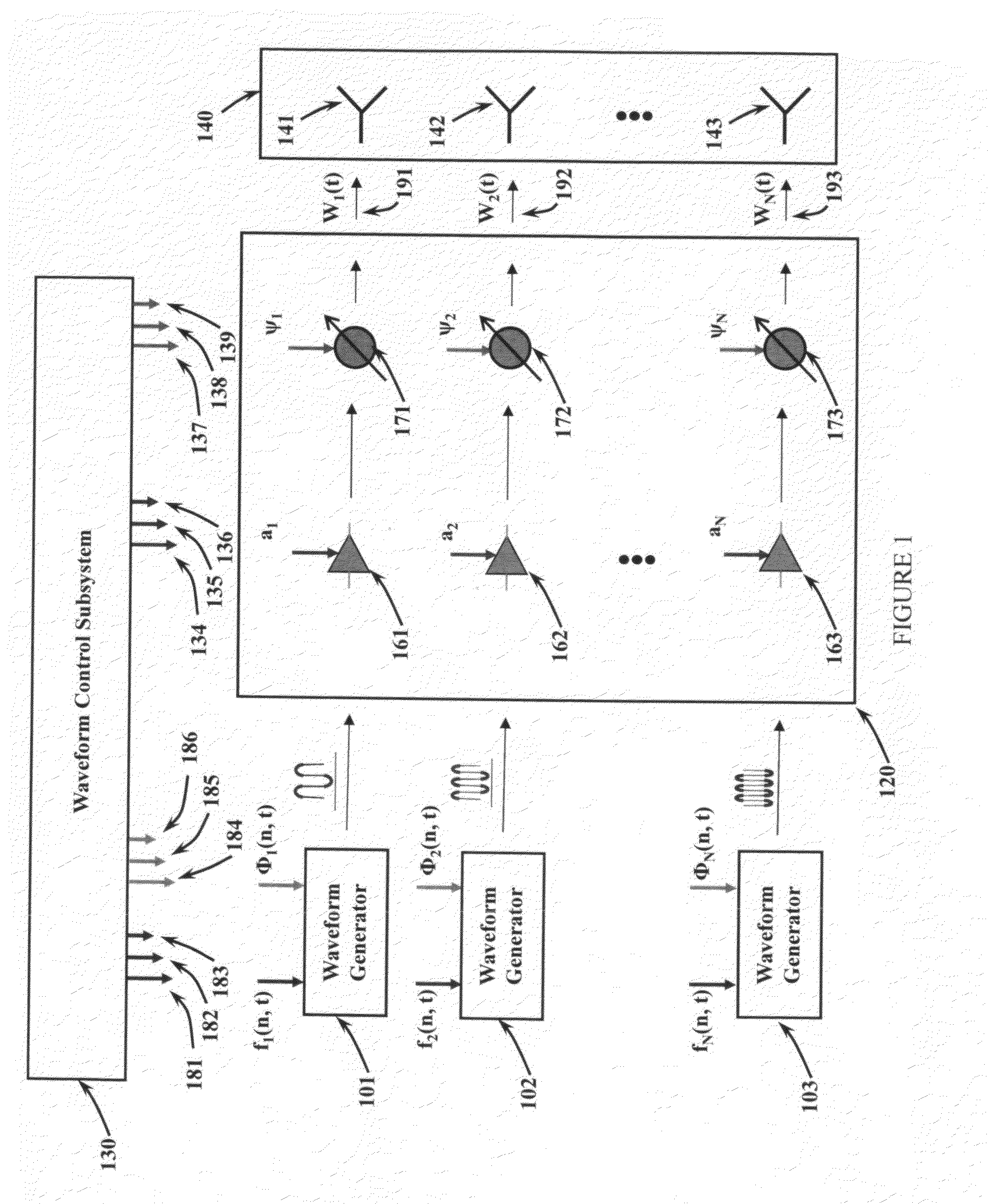
[0043]Referring to FIG. 1, the key components of a method and apparatus for simultaneous synthetic aperture radar and moving target indication include a plurality of waveform generators 101, 102, 103, a transmitter / receiver module 120, a waveform control subsystem 130, and a radiating element array 140.

[0044]A first, second through nth waveform generator 101, 102, 103 synthesize signals to be transmitted. The signals output from each of the waveform generators 101, 102, 103 are applied to a transmitter / receiver module 120. The waveform generators 101, 102, 103, the first, second, through nth inputs and outputs 191, 192, 193 of the transmitter / receiver module 120, and the first, second and nth antenna radiating / receiving elements 141, 142, 143 are interconnected such that any first, second, and nth waveform generator output can be applied to any and all first, second, through nth spatial channels. The outputs 191, 192, 193 of the transmit / receive module 120 are provided to a like plu...


PUM


Abstract

Method and apparatus for simultaneous synthetic aperture radar and moving target detection. A plurality, of independent radio frequency signals are generated and applied to separate radiating/receiving antenna elements. Signals are generated as basis functions, such that moving target detection and synthetic aperture radar signals are constructed from individual waveform components in space, time, frequency, and coding. Waveform components are sorted and combined at reception. Received data is simultaneously processed to extract synthetic aperture radar images and moving target indication detections.

Description

PRIORITY CLAIM UNDER 35 U.S.C. §119(e)[0001]This patent application claims the priority benefit of the filing date of provisional application Ser. No. 60 / 795,979, having been filed in the United States Patent and Trademark Office on Apr. 28, 2006 and now incorporated by reference herein.Cross-Reference to Related Applications[0002]The present patent application is a continuation-in-part and claims priority from related, co-pending, and commonly assigned U.S. patent application Ser. No. 12 / 456,269, which is in turn a continuation-in-part application of and claims priority from related, co-pending, and commonly assigned U.S. patent application Ser. No. 11 / 725,939 filed on Apr. 25, 2007, entitled “Method and Apparatus for Simultaneous Synthetic Aperture Radar and Moving Target Indication”, now U.S. Pat. 7,646, 326, all by Paul Antonik and Michael C. Wicks. Accordingly, U.S. patent applications Ser. No. 12 / 456,269 and 11 / 725,939 and U.S. Pat. 7,646, 326 are herein incorporated by refere...

Claims


Application Information

Patent Timeline
IPC IPC(8): G01S13/90
CPCG01S7/282G01S7/288G01S2013/0245G01S13/9029G01S13/28G01S13/9054G01S13/9052
Inventor ANTONIK, PAULWICKS, MICHAEL C.
Owner ANTONIK PAUL
Why Eureka
Try Eureka