Electronic horn for motor vehicle or motor boat

A technology for electronic horns and motor vehicles, which is applied to sound-producing apparatuses, instruments, etc., can solve the problems of complex horn structure, low energy utilization rate, unfavorable energy conservation and environmental protection, etc. Effect

Active Publication Date: 2014-02-12
万喻
View PDF7 Cites 2 Cited by
  • Summary
  • Abstract
  • Description
  • Claims
  • Application Information

AI Technical Summary

Problems solved by technology

However, this electromagnetic sounding system usually has low electroacoustic conversion efficiency, resulting in low energy utilization rate, which is not conducive to energy saving and environmental protection. Moreover, electromagnetic speakers are often complex in structure and prone to electromagnetic interference

Method used


Image

  • Electronic horn for motor vehicle or motor boat
  • Electronic horn for motor vehicle or motor boat

Examples


Embodiment 1

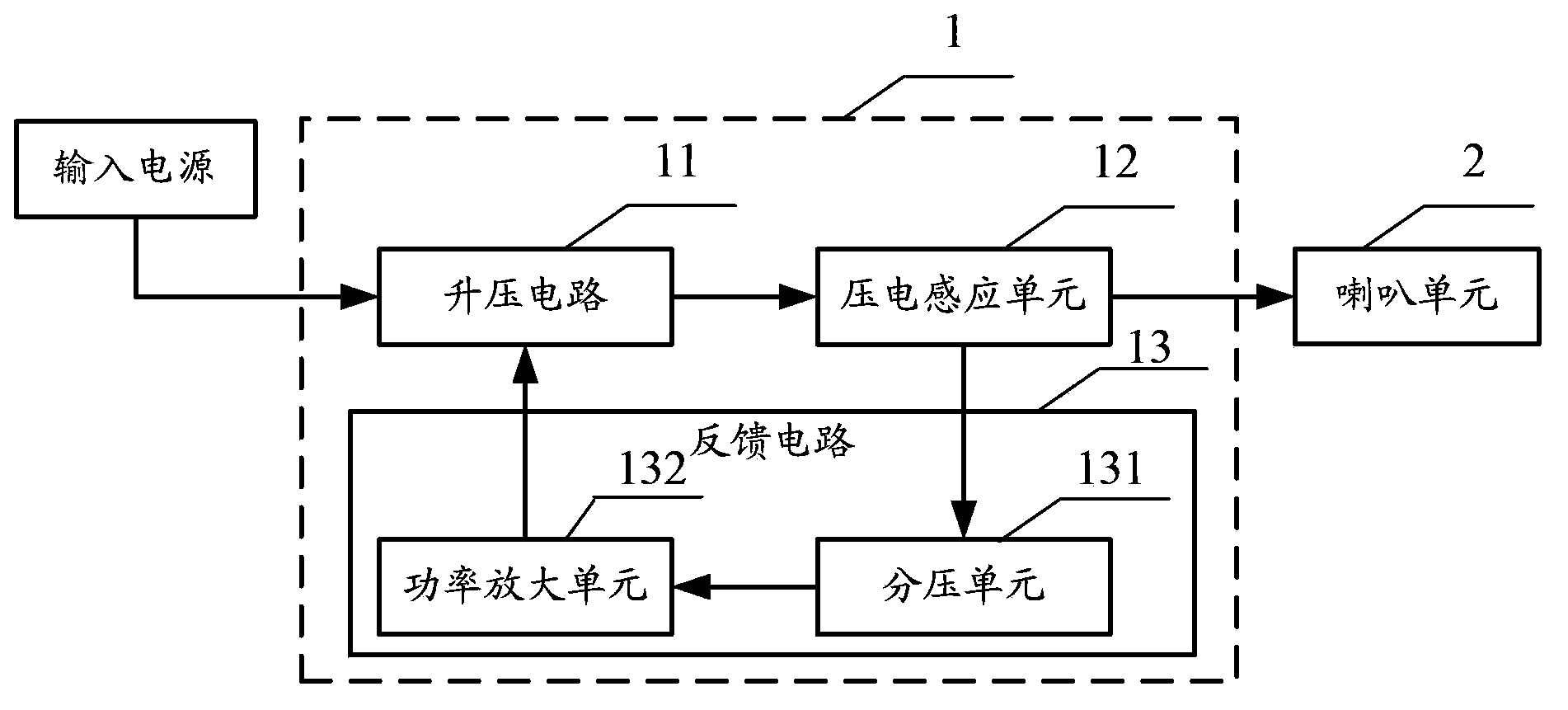
[0016] figure 1 It is the functional block diagram of the motor vehicle marine electronic horn provided by the present embodiment, as figure 1 As shown, the electronic horn for motor vehicles and ships in this embodiment includes a drive device 1 and a horn unit 2 .

[0017] Wherein, the driving device 1 includes a boost circuit 11 , a piezoelectric sensing unit 12 , and a feedback circuit 13 .

[0018] The boost circuit 11 is used for boosting the input voltage to generate a boosted driving voltage. One end of the input end of the boost circuit 11 is connected to the input power supply, and the other end is connected to the feedback circuit 13, so that the working state of the boost circuit 11 is controlled by the feedback circuit 13, and the output terminal of the boost circuit 11 and the piezoelectric induction unit 12 connected to provide the boosted driving voltage to the piezoelectric sensing unit 12 to provide the piezoelectric sensing unit 12 with a driving voltage o...

Embodiment 2

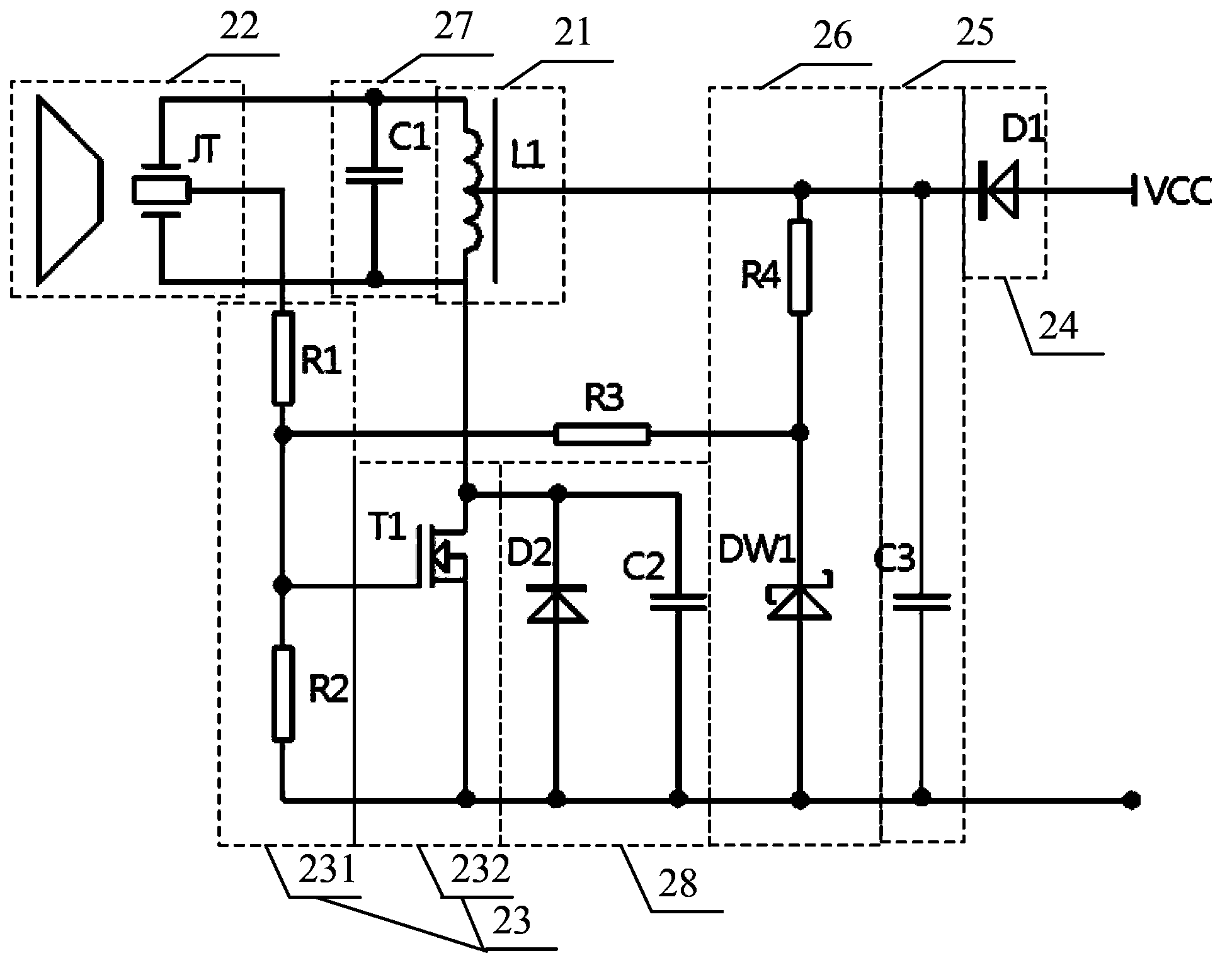
[0025] figure 2 It is the circuit schematic diagram of the motor vehicle marine electronic horn provided by the present embodiment, as figure 2 As shown, the motor vehicle marine electronic horn provided in this embodiment includes a boost circuit 21, a piezoelectric horn 22, a feedback circuit 23, a polarity protection circuit 24, a filter circuit 25, a voltage stabilizing circuit 26, a resonant circuit 27 and an overvoltage protection circuit 28 .

[0026] The boost circuit 21 is used for boosting the input voltage to generate a boosted driving voltage. The boost circuit 21 includes a boost transformer L1, one end of the primary coil of the boost transformer L1 is connected to the input voltage, and the other end of the primary coil of the boost transformer L1 is connected to the output of the feedback circuit, thus the working state of the boost circuit Controlled by the feedback circuit; the secondary coil of the step-up transformer L1 is output to the two poles of the...


PUM


Abstract

The invention relates to an electronic horn for a motor vehicle or a motor boat. The electronic horn for the motor vehicle or the motor boat comprises a booster circuit, a piezoelectric induction unit, a feedback circuit and a horn unit, wherein the booster circuit is used for carrying out boost processing on input voltage to generate boosted driving voltage, the piezoelectric induction unit is used for receiving the driving voltage generated by the booster circuit to drive a vibrating diaphragm of the horn unit to vibrate so as to give out a sound, and generating induction voltage with the oscillation frequency, the feedback circuit is used for receiving the induction voltage, and building oscillation switch-on and switch-off according to the induction voltage to control the working state of the booster circuit, the horn unit is used for vibrating to give out a sound together with the piezoelectric induction unit when the piezoelectric induction unit is driven by the driving voltage, when operation is carried out, the feedback circuit is controlled by the induction voltage to carry out switch-on and switch-off according to the oscillation frequency, and the booster circuit generates the driving voltage with the oscillation frequency. The electronic horn for the motor vehicle or the motor boat is high in electroacoustic conversion efficiency, improves the energy utilization rate, and is beneficial to energy saving and environmental protection.

Description

technical field [0001] The invention relates to an electroacoustic device, in particular to an electronic horn for motor vehicles and ships. Background technique [0002] The horn is an electroacoustic transducer that converts electrical signals into acoustic signals and spreads them into the air. Since the birth of the automobile in 1886, the car horn has become one of the parts that must be installed on the car. During the driving process of the car, the driver sends out the necessary sound signals according to the needs and regulations to warn pedestrians and attract the attention of other vehicles to ensure traffic safety. [0003] With the development of automobile technology, many parts of automobiles are developing in the direction of electronics, and car horns have also undergone various improvements, and have experienced generations of advancements such as manual, pneumatic, electric, and electronic. In addition to pneumatic horns, whether it is an electromechanic...

Claims


Application Information

Patent Timeline
Patent Type & Authority Applications(China)
IPC IPC(8): G10K9/122
Inventor 万喻
Owner 万喻
Why Eureka
Try Eureka