Press type vacuum nozzle

A vacuum suction pen and push-type technology, which is applied in the electronic field, can solve the problems of electronic components falling off and inconvenient use, and achieve the effect of easy adsorption, simple design and convenient use

Inactive Publication Date: 2014-02-12
KUNSHAN DAJIU ELECTRONICS
View PDF3 Cites 5 Cited by
  • Summary
  • Abstract
  • Description
  • Claims
  • Application Information

AI Technical Summary

Problems solved by technology

[0002] Vacuum suction pens are widely used in the process of packaging and installing electronic components. The existing vacuum suction pens generally absorb electronic components by directly squeezing the pump air tube. The pump air pipe, after the components reach the designated position, squeeze the pump air pipe again, which is inconvenient to use. At the same time, the pump air pipe is squeezed to different degrees, and the suction is different. When the suction is insufficient, the electronic components may fall off during the transmission process

Method used


Image

  • Press type vacuum nozzle

Examples


Embodiment Construction

[0012] The present invention will be further described below in conjunction with the accompanying drawings.

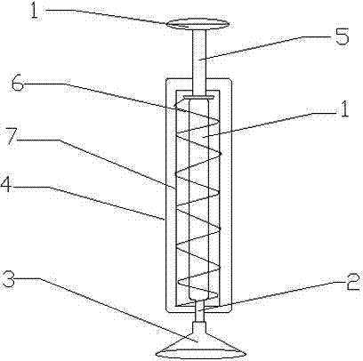
[0013] The press-type vacuum suction pen includes a pump tube 1, a connector 2, a suction cup 3 and a pen holder 4. The pump tube 1 communicates with the suction cup 3 through the connector 2. The pump tube 1 is arranged inside the pen holder 4, and the pen holder 4 includes a pressing end and a suction cup. The connector 2 protrudes from the suction cup end, the pressing end is provided with a pressing rod 5, the pressing rod 5 protrudes from the pressing end, and the pressing rod 5 is connected with a spring 6.

[0014] The pump air tube 1 is arranged in the spring 6, and a cylindrical accommodating cavity 7 is arranged between the spring 6 and the pen holder 4. The spring 6 is arranged in the accommodating cavity 7, and the accommodating cavity 7 can place the spring 6 during the pressing process. bending.

[0015] The use process of the present invention is as fol...


PUM


Abstract

The invention discloses a press type vacuum nozzle which comprises an air pumping pipe, a connector, a sucker and a pen holder. The air pumping pipe is connected with the sucker through a connector, the air pump pipe is arranged in the pen holder, the connector extends out of the sucker end of the pen holder, a press rod is arranged at the press end of the pen holder, the press rod extends out of the press end, the press rod is connected with a spring, the air pumping pipe is positioned in the spring, and a column-shaped accommodating cavity is arranged between the spring and the pen holder. The press type vacuum nozzle can suck electronic elements by pressing the press rod at the top end of the pen holder. The air pumping pipe needn't be pressed always in a using process, so that the press type vacuum nozzle is convenient to use and simple in design.

Description

technical field [0001] The invention relates to the field of electronic technology, and in particular to a vacuum suction pen for pressing electronic components. Background technique [0002] Vacuum suction pens are widely used in the process of packaging and installation of electronic components. The existing vacuum suction pens generally absorb electronic components by directly squeezing the pump air tube. Before sucking electronic components, squeeze the pump air tube, align the electronic components, and release them. Pump air tube, after the component reaches the designated position, squeeze the pump air tube again, which is inconvenient to use. At the same time, the pump air tube is squeezed to different degrees, and the suction force is different. When the suction force is insufficient, the electronic components may fall off during the transmission process. SUMMARY OF THE INVENTION [0003] The invention overcomes the deficiencies of the prior art, and provides an e...

Claims


Application Information

Patent Timeline
Patent Type & Authority Applications(China)
IPC IPC(8): H01L21/683
CPCH01L21/6838
Inventor 王枫
Owner KUNSHAN DAJIU ELECTRONICS
Why Eureka
Try Eureka