A precoding method and device for a coordinated multipoint transmission system
A multi-point transmission and precoding technology, which is applied in the field of communication, can solve problems such as large loss of cooperative UEs, interference, and influence on demodulation of cooperative UEs, and achieve the effects of improving throughput, reducing interference, and ensuring the quality of received signals
- Summary
- Abstract
- Description
- Claims
- Application Information
AI Technical Summary
Problems solved by technology
Method used
Image
Examples
Embodiment 1
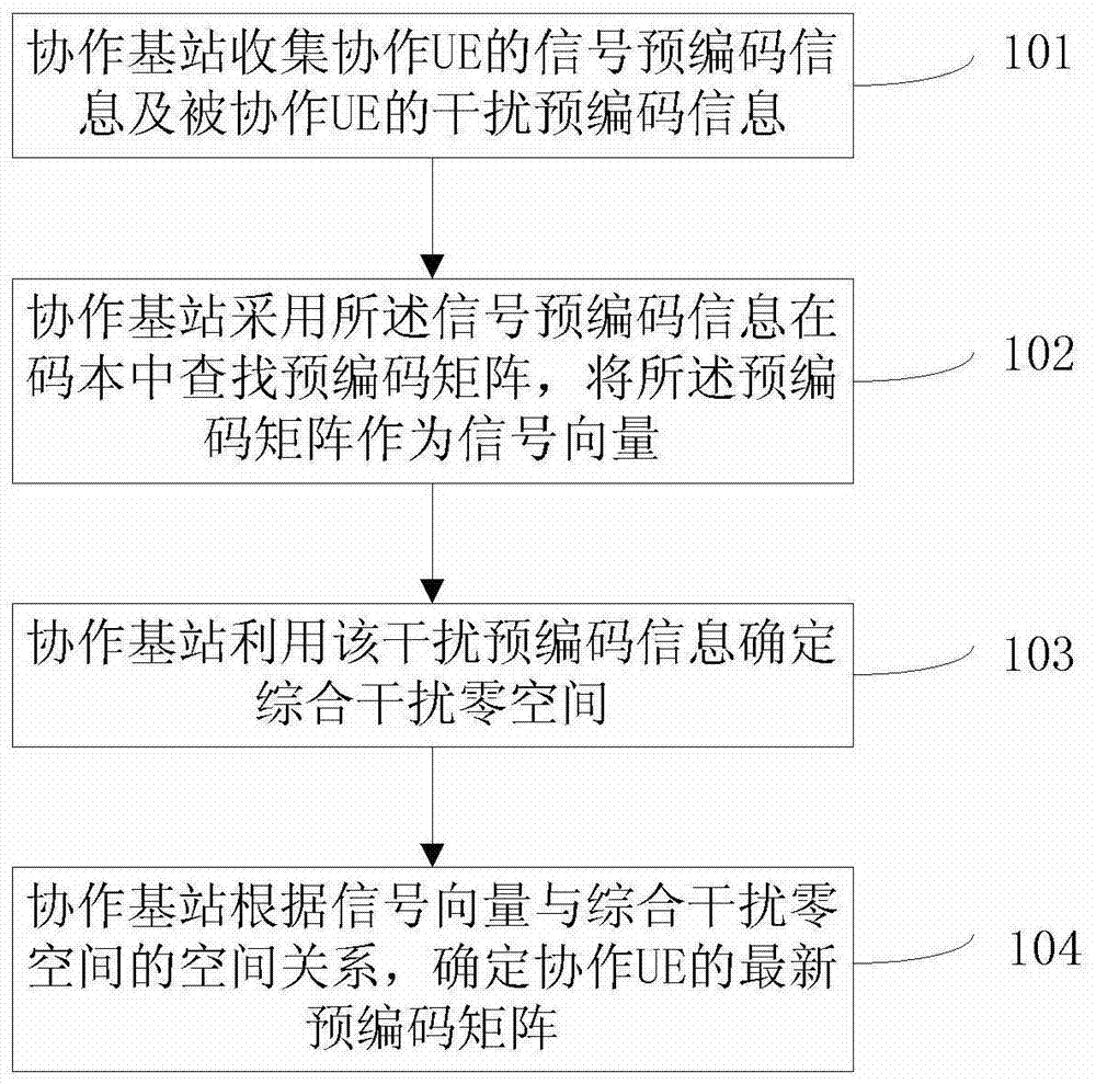
[0057] This embodiment provides a method for determining a precoding matrix, figure 1 It is a schematic flowchart of a method for generating a precoding matrix of a cooperative UE, specifically including steps 101-104:
[0058] Step 101, the coordinated base station collects the signal precoding information of the cooperating UE and the interference precoding information of the coordinated UE;
[0059] Wherein, the signal precoding information is obtained by matching in the codebook according to a certain principle by using the channel between the UE belonging to the coordinated base station (hereinafter referred to as the coordinated UE) and the coordinated base station (hereinafter referred to as the signal channel). The signal precoding information includes a precoding matrix index (Precoding Matrix Index, PMI for short) and a rank index (Rank Index, RI for short).
[0060] Among them, the interference precoding information is sent from other UEs allocated with the same fr...
Embodiment 2
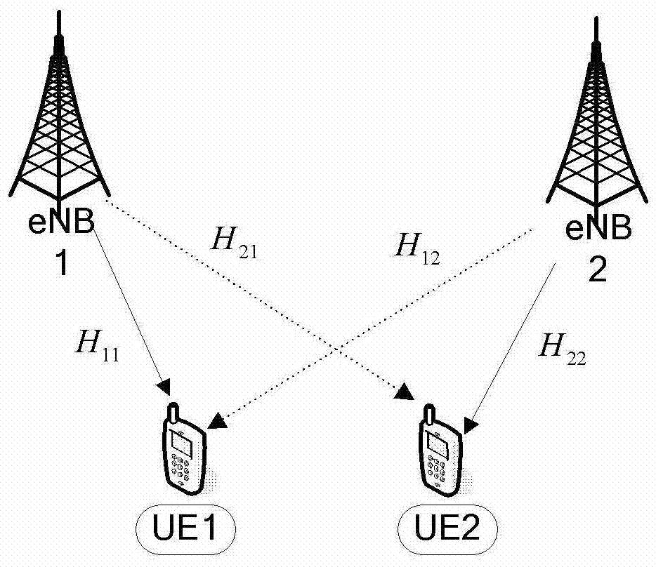
[0098] This embodiment provides a method for calculating the precoding of the coordinated UE by using the coordinated multi-point transmission technology in the case of two cells. image 3 It is a scenario where coordinated multipoint transmission is adopted in two cells and two UEs in this embodiment. In this embodiment, the base station side uses 4 antennas to send data, and the UE side uses 2 antennas to receive data. UE1 belongs to eNB1, and UE2 belongs to eNB2. UE1 and UE2 are allocated the same frequency resources. UE1 is at the cell edge and is a coordinated UE, UE2 is a coordinated UE, eNB1 is a coordinated base station, and eNB2 is a coordinated base station. The channel between UE1 and eNB2 is H 12 , the channel between UE2 and eNB2 is H 22 . h 12 、H 22 Both are 2x4 matrices. Since the two UEs are allocated the same frequency resources and UE1 is at the cell edge close to eNB2, when eNB2 sends data to UE2, it will affect the data reception of UE1. Therefore,...
Embodiment 3
[0155] This embodiment provides a method for calculating precoding by using the coordinated multi-point transmission technology in the situation of 3 cells and 3 UEs. Figure 4 It is a scenario where coordinated multipoint transmission is adopted in 3 cells and 3 UEs. Wherein, the base station side uses 4 antennas to transmit data, and the UE side uses 2 antennas to receive data. UE1 belongs to eNB1, UE2 belongs to eNB2, and UE3 belongs to eNB3. UE1, UE2 and UE3 are allocated the same frequency resource. Both UE1 and UE2 are at the cell edge and are coordinated UEs, UE3 is a coordinated UE, both eNB1 and eNB2 are coordinated base stations, and eNB3 is a coordinated base station. The channel between eNB3 and UE1 is H 13 , the channel between eNB3 and UE2 is H 23 , the channel between eNB3 and UE3 is H 33 . h 13 、H 23 、H 33 Both are 2x4 matrices. Since the three UEs are allocated the same frequency resources and both UE1 and UE2 are located at the cell edge close to eN...
PUM
 Abstract
Description
Claims
Application Information
 - R&D
- Intellectual Property
- Life Sciences
- Materials
- Tech Scout
- Unparalleled Data Quality
- Higher Quality Content
- 60% Fewer Hallucinations
Browse by: Latest US Patents, China's latest patents, Technical Efficacy Thesaurus, Application Domain, Technology Topic, Popular Technical Reports.
© 2025 PatSnap. All rights reserved.Legal|Privacy policy|Modern Slavery Act Transparency Statement|Sitemap|About US| Contact US: help@patsnap.com


