Method for machining fuel manifold with nozzles and of welding structure

A fuel manifold and welding structure technology, applied in welding equipment, metal processing equipment, manufacturing tools, etc., can solve the problems of out of tolerance nozzle housing position, large residual stress, fracture failure, etc., and achieve improved welding deformation and stable quality. , the effect of qualified dimensional accuracy

Active Publication Date: 2014-02-19
SHENYANG LIMING AERO-ENGINE GROUP CORPORATION
View PDF5 Cites 21 Cited by
  • Summary
  • Abstract
  • Description
  • Claims
  • Application Information

AI Technical Summary

Problems solved by technology

Due to the small diameter D caused by welding deformation, the position of the nozzle housing is out o

Method used


Image

  • Method for machining fuel manifold with nozzles and of welding structure
  • Method for machining fuel manifold with nozzles and of welding structure
  • Method for machining fuel manifold with nozzles and of welding structure

Examples


Embodiment Construction

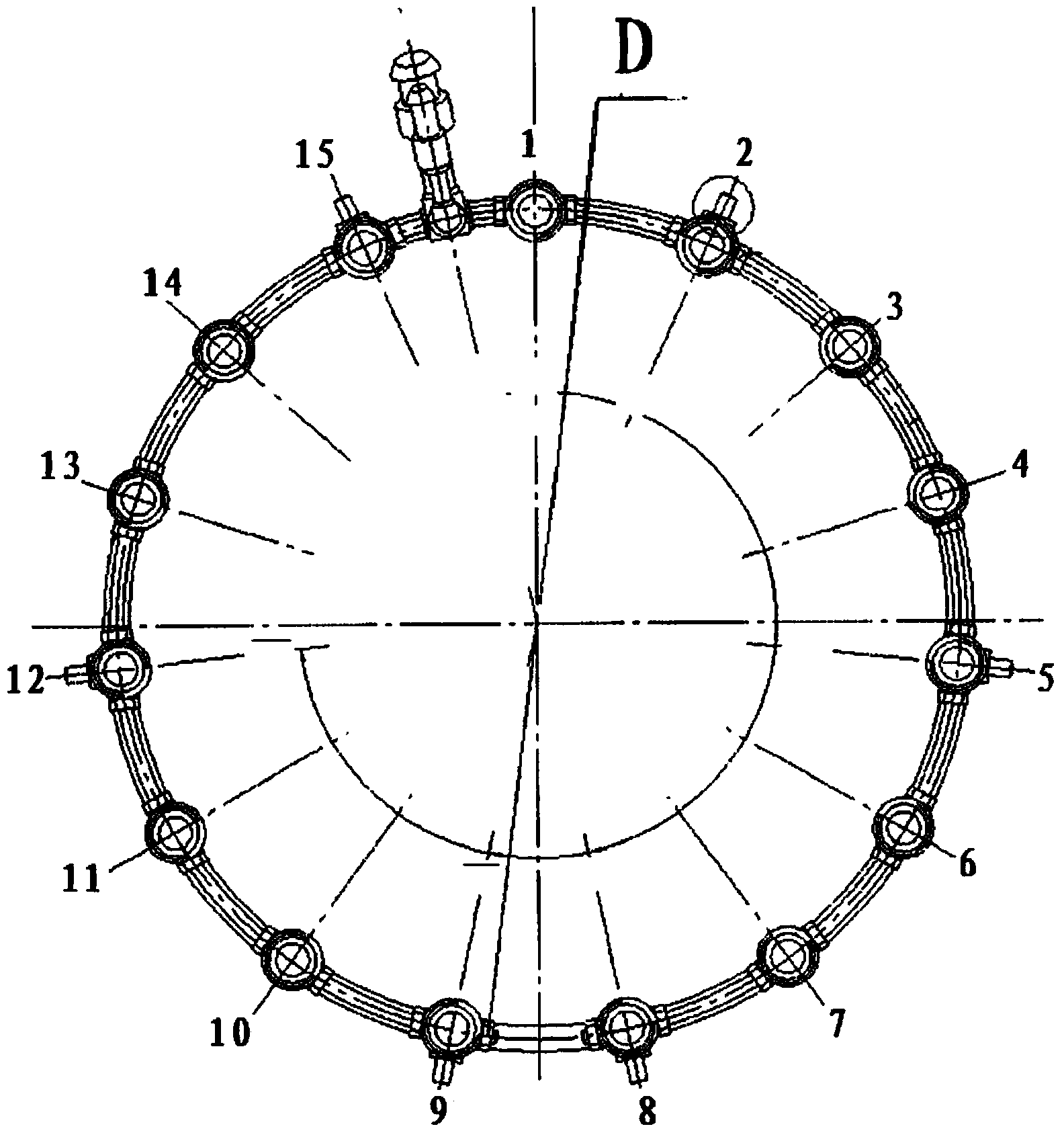
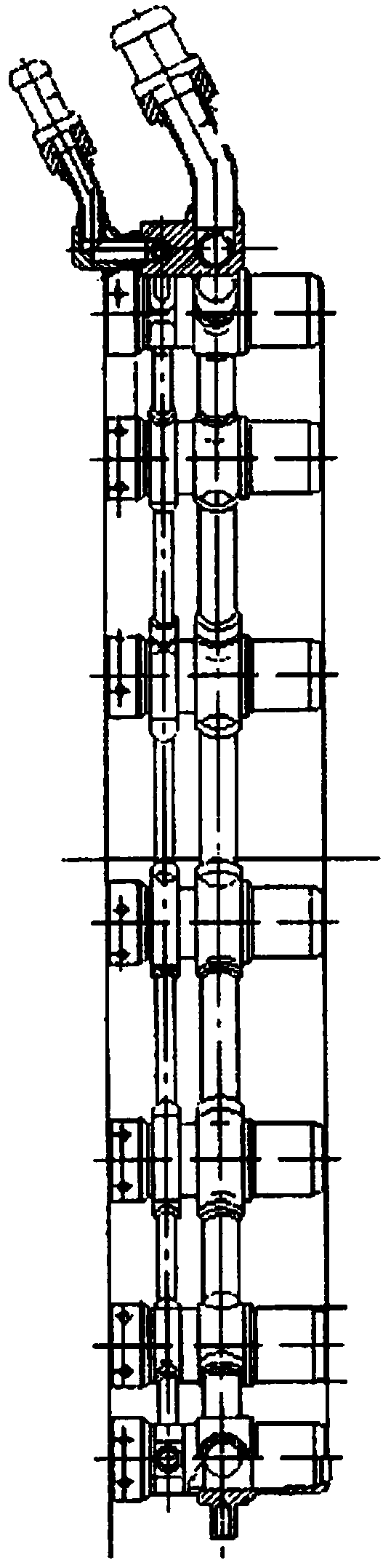
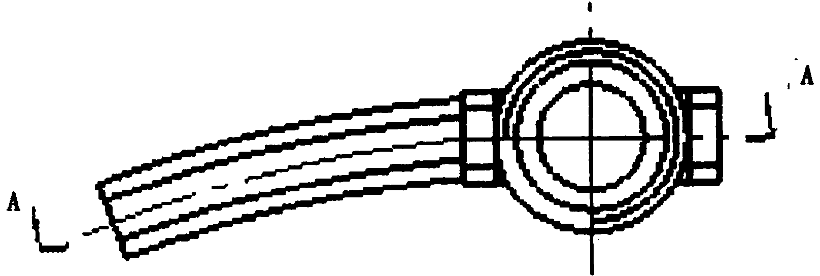
[0023] The present invention will be described in detail below with reference to the drawings, such as Figure 1-1 to Figure 6 As shown, the part consists of 15 nozzle housings 1, 2, 3, 4, 5, 6, 7, 8, 9, 10, 11, 12, 13, 14, 15 (6 of which have mounting pins, respectively It is made by argon arc welding of 2, 5, 8, 9, 12, 15) and Φ8 and Φ15 pipes. At the same time, the main and auxiliary oil inlet pipes are welded, and there are as many as 65 welds. The drawing of the manifold requires that the position of 15 nozzle housings and 6 mounting pins should not be greater than 0.5. In the initial stage of the development process, the nozzle shell and the tube were assembled and welded into a manifold ring at one time, and 6 mounting pins were bored after heat treatment and correction. Due to the smaller diameter D caused by welding deformation, the out-of-tolerance position of the nozzle housing and the larger residual stress, fracture failure occurred during the engine test run.

[0...


PUM


Abstract

The invention discloses a method for machining a fuel manifold with nozzles and of a welding structure. The method includes the welding step, the thermal treatment step and the boring step. Assembly and positioned welding are conducted on each nozzle shell and each pipe at the position, located on the middle arc increasing position, of a small-section welding clamp, and 15 sets of welded nozzle assemblies are formed and corrected at the position; assembly and positioned welding are conducted on every two sets of nozzle assemblies at the middle arc increasing position of the welding clamp according to the general drawing position, and the welded nozzle assemblies are corrected on the original welding clamp; in the process of forming half rings of the manifold, assembly and positioned welding are conducted on each welding seam at the middle arc increasing position of the welding clamp, and the welded welding seams are corrected on the original welding clamp; eventually positioned welding is conducted on the two half rings on the original welding clamp, and the two welded half rings are corrected. The method has the advantages that the welding deformation phenomenon is obviously improved, size accuracy is qualified, the method smoothly passes long test evaluation, the quality is stable, and no fracture failure in the engine test process occurs.

Description

Technical field [0001] The invention relates to the field of welding, in particular to a method for processing a fuel header with a welding structure with nozzles. Background technique [0002] The working fuel main pipe of an aero engine is mainly a ring-shaped welded structure composed of a nozzle housing and a pipe, as shown in Figure 1. This part consists of 15 nozzle housings 1, 2, 3, 4, 5, 6, 7, 8, 9, 10, 11, 12, 13, 14, 15 (6 of which have mounting pins, respectively 2, 5, 8, 9, 12, 15) are welded with Φ8 and Φ15 pipes by argon arc welding. At the same time, the main and auxiliary oil inlet pipes are also welded, and there are as many as 65 welds. The drawing of the manifold requires that the position of 15 nozzle housings and 6 mounting pins should not be greater than 0.5. In the initial stage of the development process, the nozzle shell and the tube were assembled and welded into a manifold ring at one time, and 6 mounting pins were bored after heat treatment and corre...

Claims


Application Information

Patent Timeline
IPC IPC(8): B23P15/00B23K9/167
CPCB23P15/00B25B11/00
Inventor 周勇杨踊杨涧石张炳海刘晓娟
Owner SHENYANG LIMING AERO-ENGINE GROUP CORPORATION
Why Eureka
Try Eureka