Machining clamp and machining method for curved surface vent groove of thin-wall sheet metal part

A processing method and technology for sheet metal parts, applied in metal processing equipment, metal processing machinery parts, manufacturing tools, etc., can solve the problems of low processing efficiency, difficult processing of parts ventilation grooves, easy to be scrapped, etc., to reduce labor intensity, The dimensional accuracy is qualified and the effect of ensuring consistency

Pending Publication Date: 2022-02-11
CHINA HELICOPTER RES & DEV INST
View PDF0 Cites 0 Cited by
  • Summary
  • Abstract
  • Description
  • Claims
  • Application Information

AI Technical Summary

Problems solved by technology

[0004] The main content of the present invention is to provide a processing fixture and processing method for curved surface ventilation grooves of thin-walled sheet metal parts, so as to solve the problems of difficulty in processing parts ventilation grooves or easy scrapping and low processing efficiency in general processing methods

Method used


Image

  • Machining clamp and machining method for curved surface vent groove of thin-wall sheet metal part
  • Machining clamp and machining method for curved surface vent groove of thin-wall sheet metal part
  • Machining clamp and machining method for curved surface vent groove of thin-wall sheet metal part

Examples


Embodiment example 1

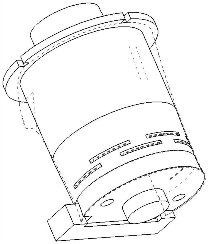
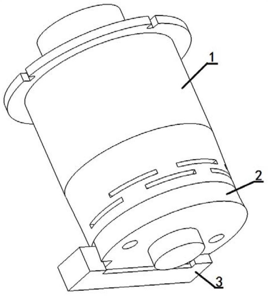
[0039] Implementation Case 1: Barrel

[0040] The barrel-shaped part is made of aluminum alloy. There are 7 ventilation grooves on the surface of the part. The groove width is 1.2mm and the length is about 50mm. It is symmetrically distributed along the central axis of the part. The center line on the molding die is led to the part, and then the barrel is fixed on the combined fixture, and then clamped as a whole on the vise of the CNC milling machine. The center line on the part is used as the reference point for processing rotation, and the milling machine is processed at the same time. The knife goes down at a constant speed, and the processing sequence is to process the left ventilation groove at the reference point rotation angle first, then rotate back to the reference point to reverse the rotation angle, and process the right ventilation groove until all the ventilation grooves are processed. During this process, a period of After the groove is machined, proceed to the ...

example 2

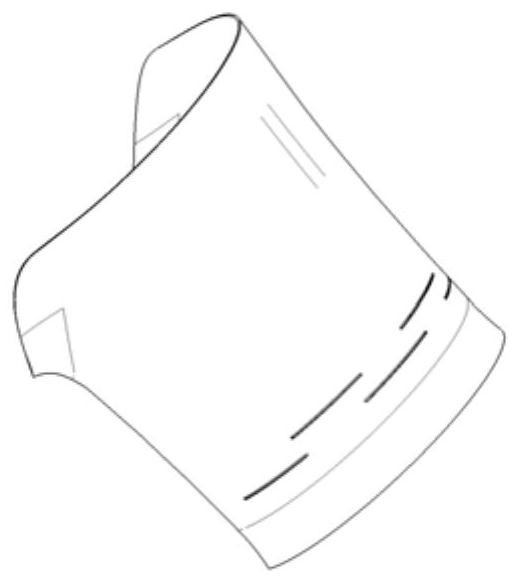
[0041] Case 2: hat brim

[0042] The material of the hat brim is aluminum alloy. There are 15 ventilation grooves on the surface of the part, the groove width is 1.2mm, and the length is 15-30mm. They are symmetrically distributed along the central axis of the part. Lead the centerline on the molding die to the part, then fix the brim piece on the combination fixture, take the centerline on the part as the reference point for processing rotation, and at the same time, the milling cutter moves down at a constant speed, and the processing sequence is based on the reference point rotation The angle is to process the left ventilation groove first, then rotate back to the reference point to reverse the rotation angle, and process the right ventilation groove until all the ventilation grooves are processed. Otherwise, processing the same groove multiple times will produce processing step marks.


PUM

PropertyMeasurementUnit
Lengthaaaaaaaaaa

Abstract

The invention belongs to the aviation sheet metal machining technology, and relates to a machining clamp and a machining method for a curved surface vent groove of a thin-wall sheet metal part. The clamp comprises a molded surface positioning block (1), a supporting base (2) and a limiting block (3); by means of the machining clamp and the machining method, a long-strip-shaped vent groove in a sheet metal part can be efficiently machined, the size precision of the vent groove is qualified, the quality is stable, and the efficiency is high; after the device and the sheet metal part are clamped on a numerical control milling platform, machining is started, an operator does not need to participate in the whole machining process until machining is finished, and compared with other vent groove machining methods, the labor intensity of the operator can be reduced to a great extent, the consistency of products is guaranteed, and the capacity meets the requirement for batch production.

Description

technical field [0001] The invention belongs to the aviation sheet metal machining technology, and relates to a processing fixture and a processing method for a curved surface ventilation groove of a thin-walled sheet metal part. Background technique [0002] The sheet metal material described in the present invention is aluminum alloy 6A02, the thickness of the part is 1.2±0.1mm, and its shape is as follows figure 1 As shown, the sheet metal part is in the shape of a semi-circular barrel, and there are seven ventilation grooves with a width of 1.2mm on the lower part of the part near the end surface. The length of the ventilation grooves is 53mm, and the ventilation grooves are arranged symmetrically from left to right. [0003] At present, there are two general processing methods for this type of ventilation groove. The first one is laser cutting ventilation groove. The laser cutting processing method is relatively fast, but the width and size of the ventilation groove cut...

Claims


Application Information

Patent Timeline
IPC IPC(8): B23C3/28B23C9/00B23Q3/06B23P15/00
CPCB23C3/28B23C9/00B23Q3/06B23P15/00
Inventor 陈家清龚佑胜王艳朱利强黄思朦
Owner CHINA HELICOPTER RES & DEV INST
Why Eureka
Try Eureka