Pneumatic automatic device for assembling binder clips

A technology of automatic device and long tail clamp, which is applied in the direction of metal processing, metal processing equipment, manufacturing tools, etc., and can solve the problems of high manpower occupation, low assembly efficiency, and high labor cost.

Inactive Publication Date: 2014-02-19
NINGBO LITAI ELECTRONICS TECH
View PDF5 Cites 13 Cited by
  • Summary
  • Abstract
  • Description
  • Claims
  • Application Information

AI Technical Summary

Problems solved by technology

[0002] The long-tail clip is also called the long-tail ticket clip. The ticket clip is a kind of clip used for holding bills and documents. The long-tail clip is a steel clip composed of a long tail and a steel clip. The existing technology uses manual tools. Insert the long tail parts of the long tail clips into the steel clip parts to assemble the long tail clip pro

Method used


Image

  • Pneumatic automatic device for assembling binder clips
  • Pneumatic automatic device for assembling binder clips
  • Pneumatic automatic device for assembling binder clips

Examples


Embodiment Construction

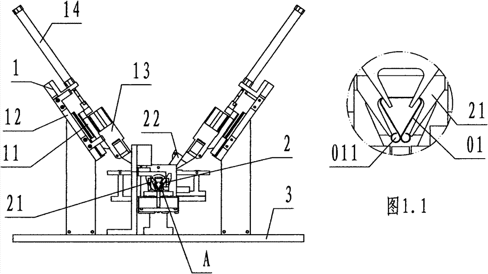
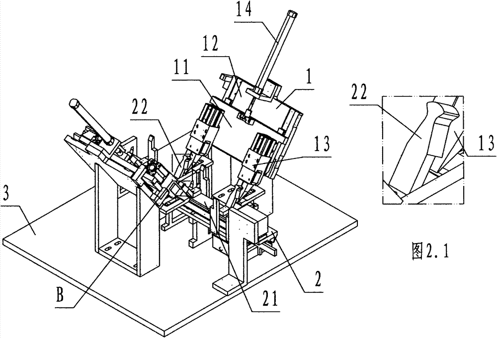
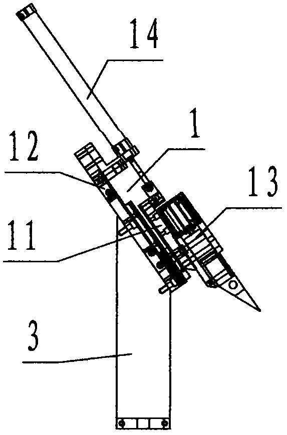
[0027] Refer to Figure 1~Figure 8 , The pneumatic automatic device for assembling long tail clamps of the present invention includes a manipulator 1, a conveying path 2, and a base 3. The manipulator 1 is composed of a sliding plate 11, a carrier plate 12, a pneumatic clamp 13, and a sliding plate cylinder 14. The carrier board 12 is a rectangular block-shaped steel plate, and the front and rear sides of the carrier board 12 are provided with up and down, mutually parallel, convex T-shaped rails called slide rails; the slide plate 11 is a rectangular block shape The front and rear sides of the sliding plate 11 are provided with T-shaped sliding grooves corresponding to the sliding rails of the carrier plate 12; the pneumatic clamp 13 is a pneumatic opening and closing clamp composed of an air cylinder and a clamp Actuator; the clamp of the pneumatic clamp 13 faces right, and the two pneumatic clamps 13 are respectively fixed on the front and rear parts of the sliding plate 11,...


PUM


Abstract

The invention discloses a pneumatic automatic device for assembling binder clips. The pneumatic automatic device comprises a mechanical hand (1), a conveying channel (2) and a base (3). The mechanical arm is provided with a sliding plate, a supporting plate, pneumatic gripping devices and a sliding plate air cylinder. The conveying channel comprises a steel clip guide groove, a steel clip air cylinder and a long-tail guide rail. The base comprises a base plate and a support. When the pneumatic automatic device works, steel clips are located in the steel clip guide groove, the steel clip air cylinder drives the steel clips to move backwards along the steel clip guide groove in a queue mode, and the long-tail guide rail is sleeved with long tails in a sliding mode; the long tails are clamped and folded through the pneumatic gripping devices, the pneumatic gripping devices assemble the long tails to the steel clips under the drive of the sliding plate air cylinder, and then the pneumatic gripping devices are reset. According to the pneumatic automatic device for assembling the binder clips, the four pneumatic gripping devices act respectively to assemble the long tails to the steel clips on the basis of the moving stride and speed of the steel clips, so that automatic assembly of the blinder clips is achieved, work strength is reduced, efficiency is improved, and cost is reduced.

Description

Technical field [0001] The invention relates to a device for producing a long tail clip, in particular to a pneumatic automatic device for assembling a long tail clip by inserting the long tail of the tail clip into a steel clip when the long tail clip is assembled. Background technique [0002] The long tail clip is also called the long tail ticket holder. The ticket holder is a clip used to hold bills and documents. The long tail clip is a steel clip composed of a long tail and a steel clip. The existing technology uses manual tools. Insert the long tail part of the long tail clip into the steel clip part to assemble the long tail clip products. Due to the huge market demand for the long tail clip, the annual production and sales are in the hundreds of millions. The manual assembly of the long tail clip has high work intensity and assembly efficiency. It is low, occupies a lot of labor, and high labor cost. Therefore, the prior art has the problems and deficiencies of high work...

Claims


Application Information

Patent Timeline
IPC IPC(8): B23P19/027
CPCB23P19/001B23P19/04
Inventor 叶建华
Owner NINGBO LITAI ELECTRONICS TECH
Why Eureka
Try Eureka