Wire rope tensioning device

A technology of tensioning device and wire rope, applied in the field of wire rope tensioning device, can solve the problem of manual operation for wire rope tensioning, and achieve the effect of high degree of automation

Inactive Publication Date: 2014-02-19
CHONGQING HENGTAI CABLE GRP
View PDF0 Cites 1 Cited by
  • Summary
  • Abstract
  • Description
  • Claims
  • Application Information

AI Technical Summary

Problems solved by technology

[0003] In order to solve the problem that current steel wire rope tensioning needs manual operation, the present invention provides a steel wire rope tensioning device, which includes an upper bottom plate 1, a lower bottom plate 2 and a tension roller 3, and the tension roller 3 is located between the upper bottom plate 1 and the tension roller 3. Between the lower bottom plates 2, there is also a hole 5 for passing the steel wire rope 4 on the tension roller 3, and a large gear 6 is also provided on the tension roller 3 below the hole 5; a reduction motor 7 is provided on the lower bottom plate 2 , the reduction motor 7 is connected with a pinion 8 meshing with the bull gear 6, and the upper bottom plate 1 is provided with a tension control sensor 9 for controlling the rotation of the pinion 8

Method used


Image

  • Wire rope tensioning device
  • Wire rope tensioning device

Examples


Embodiment Construction

[0010] All features disclosed in this specification, or steps in all methods or processes disclosed, may be combined in any manner, except for mutually exclusive features and / or steps.

[0011] Any feature disclosed in this specification, unless specifically stated, can be replaced by other alternative features that are equivalent or have similar purposes. That is, unless expressly stated otherwise, each feature is one example only of a series of equivalent or similar features.

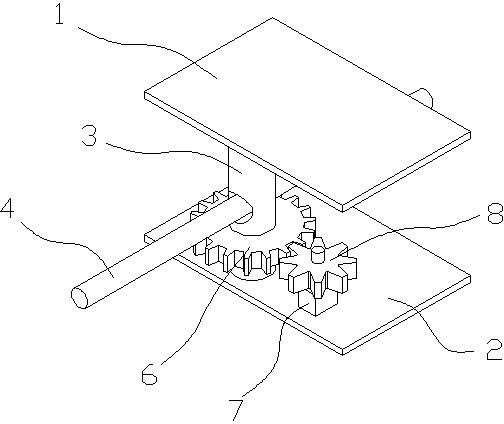
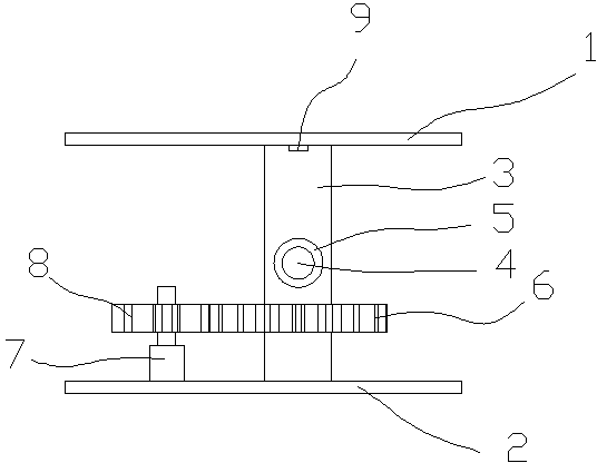
[0012] Such as figure 1 with figure 2 The wire rope tensioning device shown includes an upper bottom plate 1, a lower bottom plate 2 and a tension roller 3, the tension roller 3 is located between the upper bottom plate 1 and the lower bottom plate 2, and there is also a hole on the tension roller 3 for wearing The hole 5 of the wire rope 4, the hole 5 is perpendicular to the axis of the tension roller 3, and the tension roller 3 below the hole 5 is also provided with a large gear 6; There is a pi...


PUM


Abstract

The invention discloses a wire rope tensioning device. The wire rope tensioning device comprises an upper bottom board (1), a lower bottom board (2) and a tensioning roller (3), and is characterized in that the tensioning roller (3) is located between the upper bottom board (1) and the lower bottom board (2), the tensioning roller (3) is provided with a hole (5) through which a wire rope penetrates, a large gear (6) is arranged on the tensioning roller (3) and located below the hole (5), the lower bottom board (2) is provided with a gear motor (7), the gear motor (7) is connected with a small gear (8) meshed with the large gear (6), and the upper bottom board (1) is provided with a tension control sensor (9) for controlling the small gear (8) to rotate. The wire rope tensioning device does not need manual operation, and is high in degree of automation.

Description

technical field [0001] The invention relates to a wire rope tensioning device. Background technique [0002] During the use or production process, due to some factors, the steel wire rope will often become loose and affect the normal use. When the steel wire rope is tensioned, manual operation is generally required, and for some dangerous environments, the meeting of the operator will be There are certain security risks. Contents of the invention [0003] In order to solve the problem that current steel wire rope tensioning needs manual operation, the present invention provides a steel wire rope tensioning device, which includes an upper bottom plate 1, a lower bottom plate 2 and a tension roller 3, and the tension roller 3 is located between the upper bottom plate 1 and the tension roller 3. Between the lower bottom plates 2, there is also a hole 5 for passing the steel wire rope 4 on the tension roller 3, and a large gear 6 is also provided on the tension roller 3 below...

Claims


Application Information

Patent Timeline
IPC IPC(8): B65H77/00
Inventor 陈志田
Owner CHONGQING HENGTAI CABLE GRP
Why Eureka
Try Eureka