

A carved hole embroidery machine
An embroidery machine and hole-carving technology, applied in embroidery machines, embroidery machine mechanisms, and automatically controlled embroidery machines, etc., can solve the problems of slow cutting speed, low punching efficiency, and unclean cutting surfaces, and improve cutting speed. , Improve the punching efficiency and punching quality, and ensure the clean effect
- Summary
- Abstract
- Description
- Claims
- Application Information
AI Technical Summary
Problems solved by technology
Method used
Image

Examples
Embodiment Construction
[0028] Combine below Figure 3 to Figure 11 Examples of the present invention will be described in detail.
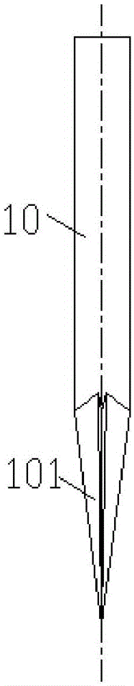
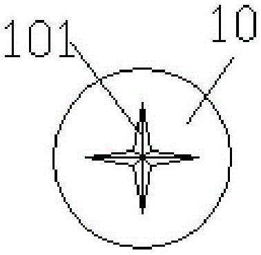
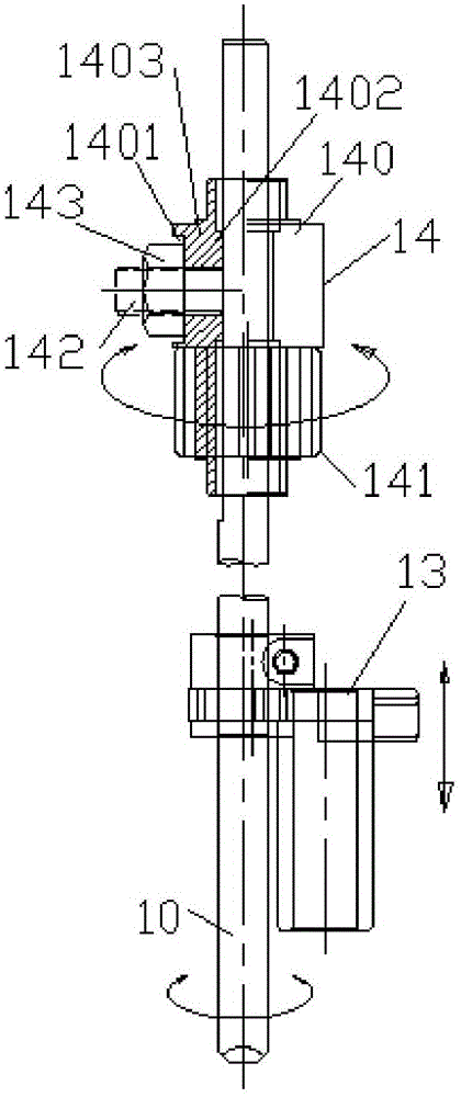
[0029] An engraved embroidery machine includes a knife bar 1, a knife head 10 is provided at the bottom of the knife bar, and a knife edge portion 101 is provided at the head end of the knife head, and the knife bar 1 is connected with a knife bar driving structure. A needle plate 2 is provided below the knife head 10, and a needle plate hole 20 is arranged on the needle plate 2. The cloth 4 is placed on the needle plate 2. into the needle plate hole 20. Wherein, in order to prevent the cloth from being rolled into the needle plate hole 20 , the knife bar 1 is provided with a cloth pressing structure, and the needle plate hole 20 is provided with a filling seat 3 .
[0030] Such as Figure 3 to Figure 5 In the shown cutter bar drive structure, the cutter bar 1 is provided with an up and down drive mechanism 13 above the cutter head 10, and the cutter bar 1 is provide...
PUM
 Abstract
Description
Claims
Application Information