Drain device, siphon toilet bowl and flushing method thereof

A technology for drainage devices and toilets, applied in water supply devices, flushing toilets, flushing equipment with water tanks, etc., can solve the problems of poor flushing effect of flushing water, loss of potential energy and kinetic energy, and increased water consumption, etc., to achieve convenient and fast installation , reduce water consumption, enhance the effect of scouring

Active Publication Date: 2014-02-19
JOMOO KITCHEN & BATHROOM
View PDF13 Cites 3 Cited by
  • Summary
  • Abstract
  • Description
  • Claims
  • Application Information

AI Technical Summary

Problems solved by technology

However, when the flushing water is diverted in the internal water channel of the toilet body, due to the mutual interference of the two streams of water, a part of potential energy and kinetic energy will be lost, which leads to poor flushing effect of the flushing water
Therefore, in order to flush the siphon toilet, the water consumption must be increased, which causes a waste of water resources

Method used


Image

  • Drain device, siphon toilet bowl and flushing method thereof
  • Drain device, siphon toilet bowl and flushing method thereof
  • Drain device, siphon toilet bowl and flushing method thereof

Examples


Embodiment 1

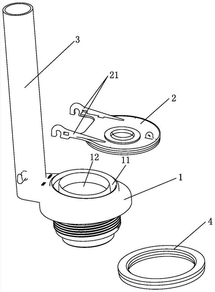
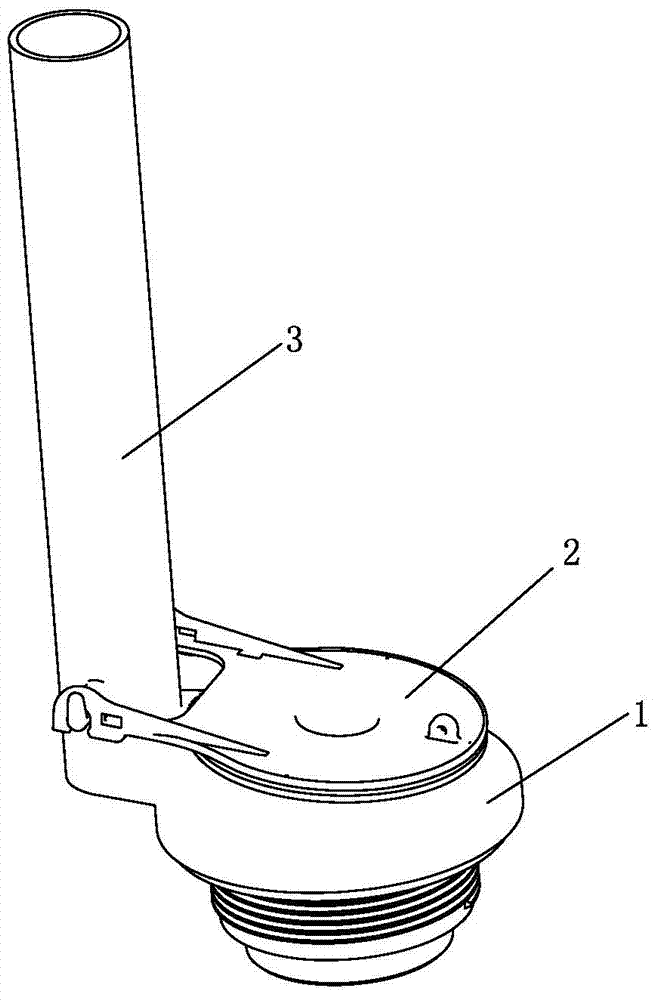
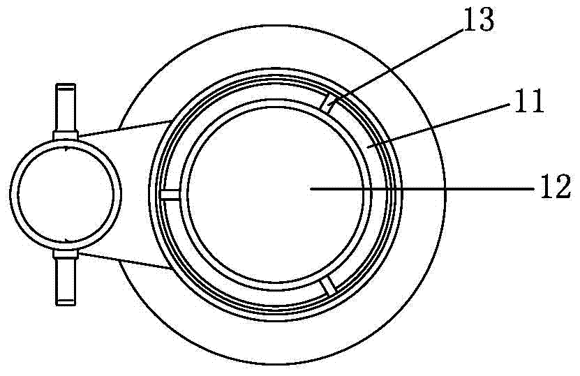
[0029] See Figure 1-Figure 4 As shown, a drainage device of the present invention includes a base 1 and a main body of the drainage device that cooperates with the base 1 and realizes the drainage action; the base 1 has a water passage that is transparent up and down. It is divided into a first water passage 11 and a second water passage 12 separated from each other.

[0030] As a preference, the drainage device of the present invention also includes an overflow pipe 3, which is arranged on the side of the base 1, and the bottom end of the overflow pipe 3 is connected to the first water passage 11 or the second water passage 11 of the base 1. The water passages 12 are connected. The above-mentioned first water passage 11 and the second water passage have an internal and external distribution structure, specifically, the first water passage 11 surrounds the outer circumference of the second water passage 12 (and vice versa), and the first water passage A number of connecting...

Embodiment 2

[0037] A drainage device of the present invention, see Figure 7 As shown, the difference between it and the first embodiment is that the first water passage 11 and the second water passage 12 of the base are in a front-to-back distribution structure. In addition, in a drainage device of the present invention, the first water passage 11 and the second water passage 12 of the base can also be in a left-right distribution structure and the like.

Embodiment 3

[0039] A drainage device of the present invention, see Figure 8 , Figure 9 As shown, the main difference between it and Embodiment 1 is: when the main body of the drainage device is a cylindrical drain valve 7, at this time, the top side wall circumference of the base 1 usually has a hollow structure 14 for water to flow into its first A water passage 11 and a second water passage 12; the bottom of the cylindrical drain valve 7 has a seal 71 that can move up and down. After the cylindrical drain valve 7 is installed on the top of the base 1, the seal 71 moves up and down The first water passage 11 and the second water passage 12 of the base can be opened or blocked simultaneously.

[0040] The drainage device of the present invention is the same as the first embodiment, and the overflow pipe 3 is also arranged on the outer surface of the base 1 . In addition, the overflow pipe can also be located in the barrel drain valve, specifically, the bottom of the overflow pipe is s...


PUM


Abstract

The invention discloses a drain device, a siphon toilet bowl and a flushing method thereof. The drain device comprises a base and a drain device body; the drain device body is matched with the base to realize draining, and the base is provided with water channels including a first water channel and a second water channel which are separated from each other. The siphon toilet bowl comprises a toilet bowl body that is provided with a spray channel, a wash-ring channel and a siphon pipe; at least, the spray channel and the wash-ring channel of the toilet bowl body are not communicated with each other during flushing of the siphon toilet bowl. The flushing method of the siphon toilet bowl includes: by the aid of the drain device, dividing water in a water tank into two water flows, including the one flowing to the spray channel of the toilet bowl body and the other one flowing to the wash-ring channel of the toilet bowl body, in the siphon toilet bowl body. The water drained from the water tank is divided into two channels without interference, so that loss of water potential energy and kinetic energy can be decreased, flushing effect can be improved, water usage can be reduced, and water is saved.

Description

technical field [0001] The invention relates to a bathroom product, in particular to a drainage device, a siphon toilet and a flushing method thereof. Background technique [0002] At present, the drainage device in the prior art generally includes a base and a drainage device body, wherein the drainage device body can be a flap cover or a cylindrical drain valve, the base has a water passage, the drainage device body is installed on the base, and Open or block its water passage. The siphon toilet of the prior art generally includes a toilet body, a water tank and the above-mentioned drainage device. The toilet body has a spray water channel and a wash ring water channel. The water passage of the base of the toilet is simultaneously communicated with the spray water channel and the wash ring water channel of the toilet body. When the siphon toilet is flushed, the flushing water in the water tank enters the toilet body through the water passage of the base, and is shunted i...

Claims


Application Information

Patent Timeline
Patent Type & Authority Applications(China)
IPC IPC(8): E03D1/34E03D1/38E03D11/02
CPCY02A20/40
Inventor 林孝发林孝山王少堂
Owner JOMOO KITCHEN & BATHROOM
Why Eureka
Try Eureka