
Rotary compressor with air suction turbocharging mechanism

A rotary compressor and turbocharging technology, applied in the field of compressors, can solve the problems of large compressor vibration and low suction efficiency, and achieve the goals of reducing vibration, improving suction pressure and suction efficiency, and good heat exchange Effect

Active Publication Date: 2014-02-19
ZHUHAI LANDA COMPRESSOR
View PDF6 Cites 5 Cited by
  • Summary
  • Abstract
  • Description
  • Claims
  • Application Information

AI Technical Summary

Problems solved by technology

[0003] The suction of a conventional compressor is a negative pressure generated by the rotation of the rollers for passive suction of the pressure difference, suction backflow caused by the interval of high-pressure air flow in the clearance volume, uneven volume change rate of the cylinder compression, and roller sweeping suction These three factors form the suction pulsation of the compressor, and the suction pulsation of the compressor easily leads to large vibration of the compressor and low suction efficiency

Method used


Image

  • Rotary compressor with air suction turbocharging mechanism
  • Rotary compressor with air suction turbocharging mechanism
  • Rotary compressor with air suction turbocharging mechanism

Examples


Embodiment Construction

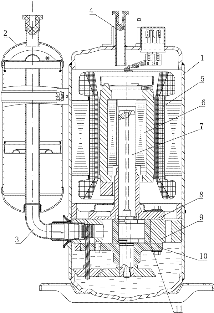
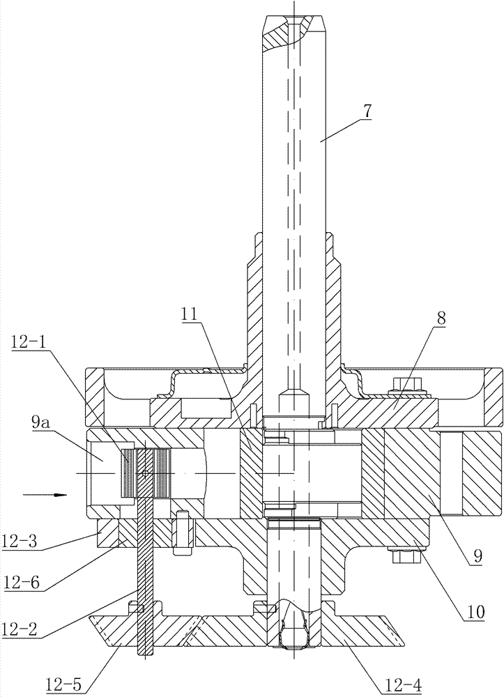
[0023] like figure 1 and figure 2 As shown, the compressor of this embodiment includes a closed casing 1, a motor assembly and a compression pump body assembly arranged inside the closed casing 1, a gas-liquid separator 2 arranged on one side of the closed casing 1, and the gas-liquid separator 2 communicates with the compression pump body of the compressor through the intake elbow 3, so that the refrigerant enters the cylinder of the compressor from the gas-liquid separator 2. The exhaust pipe 4 is arranged on the upper end of the closed casing 1, and the compressed high-temperature and high-pressure gas enters the circulation system from the exhaust pipe 4 .

[0024] The motor assembly of the present invention includes a stator 5 fixed on the upper inner wall of the closed casing 1 , and a rotor 6 rotatably arranged in the stator 5 , and the compressor shaft 7 is driven to rotate by the rotor 6 . The compression pump body assembly is arranged in the closed casing 1 below ...


PUM


Abstract

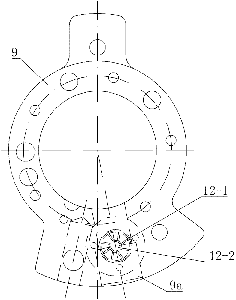
The invention discloses a rotary compressor with an air suction turbocharging mechanism. The rotary compressor comprises a sealed shell, a gas-liquid separator, an exhaust pipe and the air suction turbocharging mechanism, wherein the sealed shell is internally provided with a motor assembly and a compression pump assembly; the gas-liquid separator is communicated with the compression pump assembly through an air inlet elbow; the exhaust pipe is arranged at the upper end of the sealed shell; the motor assembly comprises a stator and a rotor, and a rotating shaft of the compressor is driven by the rotor to rotate; the compression pump assembly comprises an upper flange, an air cylinder, and a lower flange arranged along the axial direction of the rotating shaft of the compressor and a roller arranged on the rotating shaft of the compressor, and the air cylinder is provided with an air inlet pipeline connected with the air inlet elbow; and the air suction turbocharging mechanism comprises turbine blades located in the air inlet pipeline, a blade shaft for mounting the turbine blades and a driving part connecting the blade shaft and the rotating shaft of the compressor. By using a turbocharging way, the air suction pressure of the compressor is increased, the influence of clearance volume to sucked air backflow is reduced, and the volume efficiency of a pump body is increased, so that the performance of the compressor is improved.

Description

technical field [0001] The invention belongs to the technical field of compressors, in particular to a rotary compressor. Background technique [0002] Existing rotary compressors generally include a casing, a pump body, a stator, a rotor, a rotating shaft, a gas-liquid separator, a suction pipe and an exhaust pipe. When working, the rotor rotates in the stator, and drives the roller to rotate eccentrically in the cylinder through the rotating shaft. Under the eccentric rotation of the roller, the refrigerant is sucked into the cylinder and compressed until the pressure exceeds the critical pressure, and then passes through the exhaust The air pipe is output to the heat exchange system. [0003] The suction of a conventional compressor is a negative pressure generated by the rotation of the rollers for passive suction of the pressure difference, suction backflow caused by the interval of high-pressure air flow in the clearance volume, uneven volume change rate of the cylind...

Claims


Application Information

Patent Timeline
Patent Type & Authority Applications(China)
IPC IPC(8): F04C23/02F04C29/12
Inventor 林少坤
Owner ZHUHAI LANDA COMPRESSOR
Learn More