Low-temperature heat pump circulation system suitable for large temperature span and circulation method
A circulatory system, low-temperature heat technology, applied in heat pumps, superheaters, lighting and heating equipment, etc., can solve problems such as reducing compressor efficiency, increasing irreversible heat transfer losses, reducing overall system performance, etc., to reduce evaporation pressure and temperature, realize the effect of large temperature span heating, and improve system performance
- Summary
- Abstract
- Description
- Claims
- Application Information
AI Technical Summary
Problems solved by technology
Method used
Image
Examples
Embodiment 1
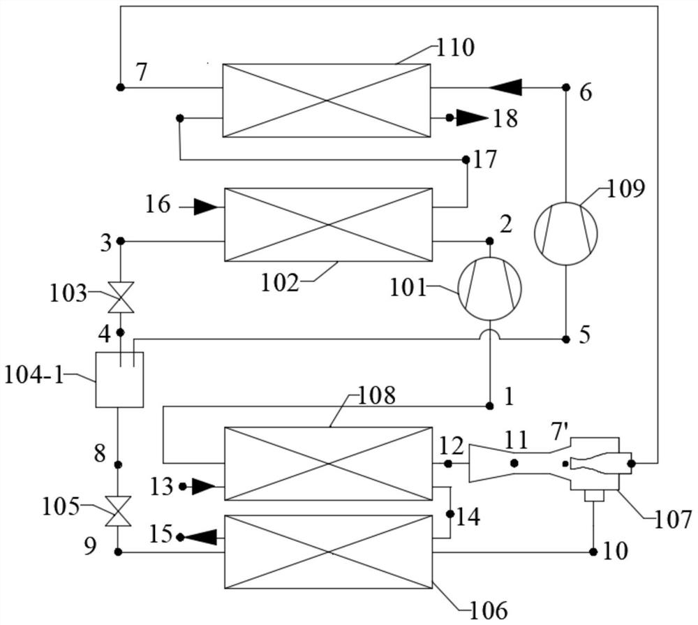
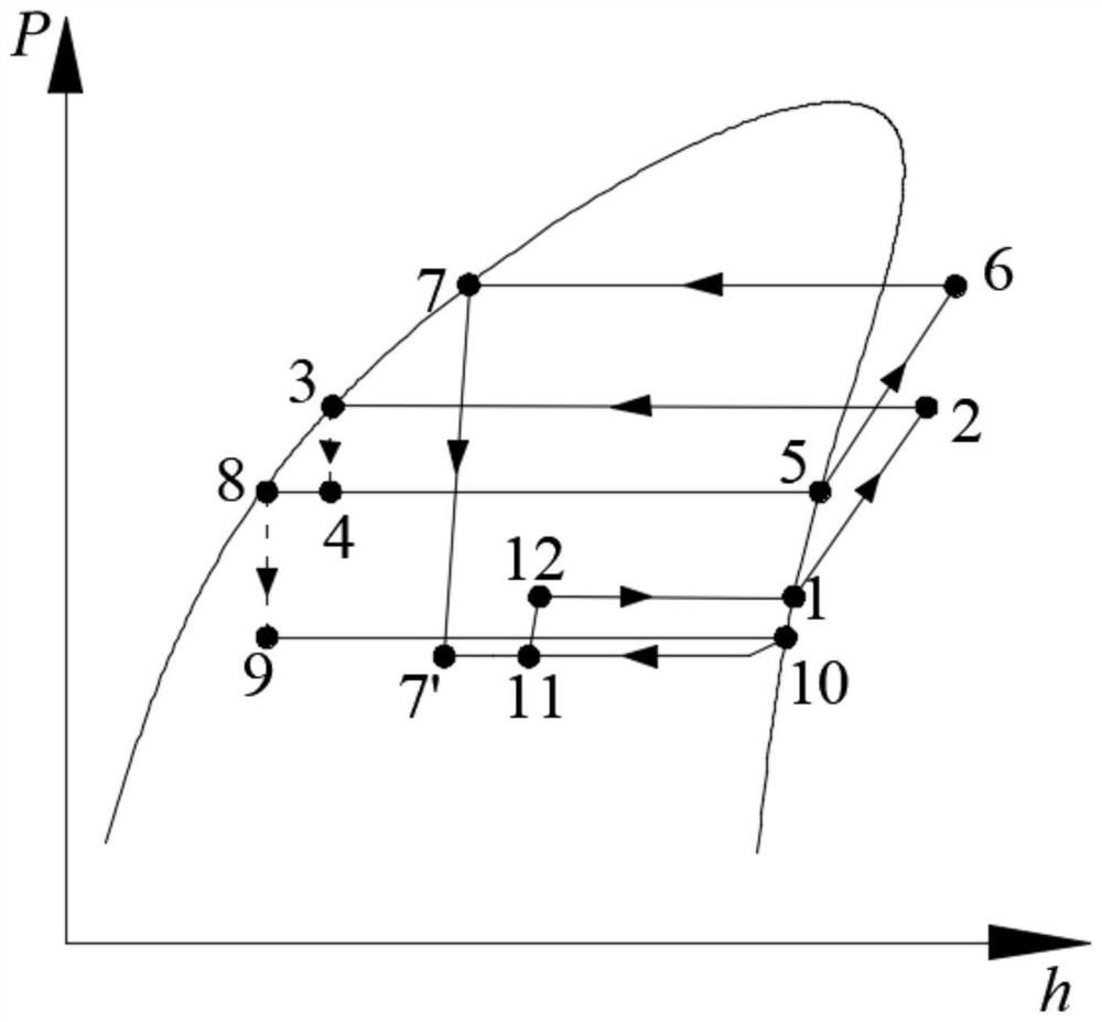
[0026] figure 1 Shown is one implementation of the invention. The exhaust port of the low-pressure side compressor 101 in the system is connected to the gas inlet of the low-temperature side condenser 102, and the gas outlet of the low-temperature side condenser 102 is connected to the inlet of the first throttling device 103; The high-temperature side condenser 110 is connected to the heat supply medium inlet; the outlet of the first throttling device 103 is connected to the inlet of the gas-liquid separator 104-1, and the gas outlet of the gas-liquid separator 104-1 is connected to the high-pressure side compressor 109 and the high-temperature side condenser 110 It is connected to the primary inlet of the ejector 107 in sequence, and the liquid outlet of the gas-liquid separator 104-1 is connected to the secondary inlet of the second throttling device 105, the low-temperature side evaporator 106 and the ejector 107 in sequence; the outlet of the ejector 107 is connected to t...
Embodiment 2
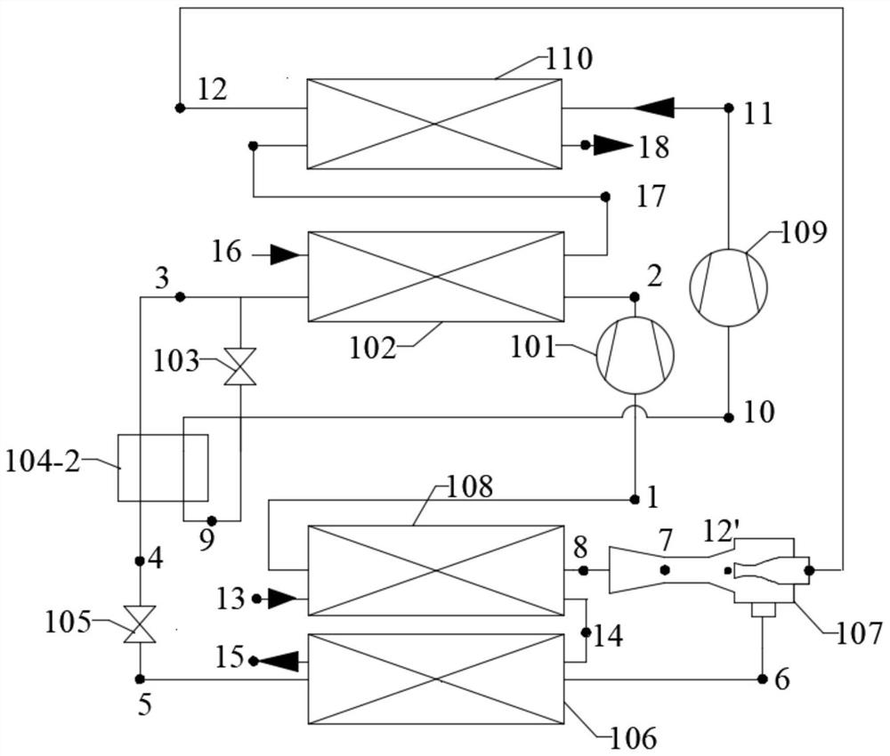
[0030] image 3 Shown is another implementation of the invention, characterized in that a regenerator is used instead of a gas-liquid separator. The exhaust port of the low-pressure side compressor 101 in the system is connected to the inlet of the low-temperature side condenser 102, and the outlet of the low-temperature side condenser 102 is divided into two routes, one of which is connected to the inlet of the high-pressure side of the regenerator 104-2, and the other is connected to the inlet of the high-pressure side of the regenerator 104-2. The inlet of the first throttling device 103 is connected; the outlet of the first throttling device 103 is connected to the inlet of the low-pressure side of the regenerator 104-2, and the outlet of the low-pressure side of the regenerator 104-2 is connected to the high-pressure side compressor 109, the high-temperature side condenser 110 and The primary inlet of the ejector 107 is connected in sequence; the outlet of the high-pressu...
PUM
 Abstract
Description
Claims
Application Information
 - R&D
- Intellectual Property
- Life Sciences
- Materials
- Tech Scout
- Unparalleled Data Quality
- Higher Quality Content
- 60% Fewer Hallucinations
Browse by: Latest US Patents, China's latest patents, Technical Efficacy Thesaurus, Application Domain, Technology Topic, Popular Technical Reports.
© 2025 PatSnap. All rights reserved.Legal|Privacy policy|Modern Slavery Act Transparency Statement|Sitemap|About US| Contact US: help@patsnap.com


