Water tank liquid level detection equipment, water tank liquid level control system and vehicle

A liquid level detection and water tank technology, applied in liquid level control, control/regulation systems, waterway systems, etc., can solve problems such as easy damage, equipment damage, false induction, etc., to improve equipment reliability and avoid safety accidents.

Inactive Publication Date: 2014-02-19
ZOOMLION HEAVY IND CO LTD
View PDF8 Cites 6 Cited by
  • Summary
  • Abstract
  • Description
  • Claims
  • Application Information

AI Technical Summary

Problems solved by technology

[0004] 1) Only when the sewage liquid level reaches the limit value, the control operation will be carried out, and the liquid level cannot be displayed in real time, and the operator cannot know the current sewage loading capacity;
[0005] 2) When the vehicle is moving, the liquid level in the water tank will shake back and forth, which may cause the float switch to move frequently, which may cause false induction. At the same time, this situation will reduce the life of the float switch and be easily damaged.
Once the float switch is damaged, it will be impossible to detect the water level of the sewage, and there may be a safety accident caused by equipment damage due to sewage overflow

Method used


Image

  • Water tank liquid level detection equipment, water tank liquid level control system and vehicle
  • Water tank liquid level detection equipment, water tank liquid level control system and vehicle
  • Water tank liquid level detection equipment, water tank liquid level control system and vehicle

Examples


Embodiment Construction

[0022] Specific embodiments of the present invention will be described in detail below in conjunction with the accompanying drawings. It should be understood that the specific embodiments described here are only used to illustrate and explain the present invention, and are not intended to limit the present invention.

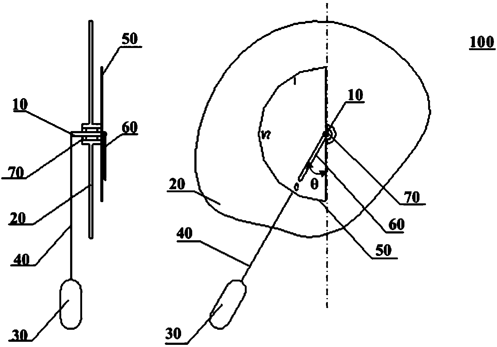
[0023] figure 1 is a schematic diagram of a water tank liquid level detection device 100 according to an embodiment of the present invention. Such as figure 1 As shown, the device includes: a rotating shaft 10, which is rotatably arranged on a water tank wall 20, and whose first end and second end are respectively located inside and outside the water tank; a float 30, which is arranged on In the water tank, the first end of the rotating shaft 10 is fixedly connected with the swing rod 40, and the float 30 rises or falls with the liquid level in the water tank, so that the swing rod 40 swings to drive the rotating shaft 10 to rotate; and indicates device (not ...


PUM


Abstract

The invention discloses water tank liquid level detection equipment, a water tank liquid level control system and a vehicle. The water tank liquid level detection equipment comprises a rotating shaft, a floater, an indicating device and a pointer, wherein the rotating shaft is arranged on the wall of a water tank in a rotatable mode, and the first end of the rotating shaft and the second end of the rotating shaft are located on the inner side of the water tank and the outer side of the water tank respectively; the floater is arranged in the water tank and fixedly connected with the first end of the rotating shaft through an oscillating bar, and the floater rises or drops along with the liquid level in the water tank so that the oscillating bar can oscillate to drive the rotating shaft to rotate; the indicating device comprises an indicating dial which is fixedly mounted on the outer wall of the water tank, wherein the second end of the rotating shaft penetrates through a center hole of the indicating dial, and the indicating dial is provided with multiple scale marks; the pointer is fixed to the second end of the rotating shaft to correspondingly point at the scale marks on the indicating dial along with the swing of the oscillating bar. The water tank liquid level detection equipment can indicate the liquid level in the water tank in real time, and brings convenience to an operator for knowing the liquid level in the water tank in real time and conducting related operation according to the real-time liquid level.

Description

technical field [0001] The invention relates to engineering machinery, in particular to a water tank liquid level detection device, a water tank liquid level control system, and a vehicle. Background technique [0002] Vehicles equipped with water tanks in the prior art, such as special vehicles that use vacuum suction (sweeping vehicles, sewage suction vehicles, comprehensive sewer maintenance vehicles, etc.), generally use the float switch installed in the sewage tank (tank) during operation. As a sensor to detect the high or low level of sewage. For example, when the float rises or falls with the sewage liquid level, one end of the float is limited by the position, and the moving object in the float touches the switch on the predetermined horizontal plane, and sends the switch contact open (close) conversion signal to detect the sewage tank (tank) Sewage water level, so as to grasp the loading capacity of sewage in real time during the operation process. If the sewage t...

Claims


Application Information

Patent Timeline
Patent Type & Authority Applications(China)
IPC IPC(8): G01F23/34E03F7/10G05D9/12
Inventor 张涛
Owner ZOOMLION HEAVY IND CO LTD
Why Eureka
Try Eureka