Image capturing system group

一种影像撷取、像侧的技术,应用在光学、仪器、光学元件等方向,能够解决不利生产制造、成本提高、拓展景深范围功能不佳等问题

Active Publication Date: 2014-02-19
LARGAN PRECISION
View PDF7 Cites 8 Cited by
  • Summary
  • Abstract
  • Description
  • Claims
  • Application Information

AI Technical Summary

Problems solved by technology

[0003] The currently developed five-piece optical system, as disclosed in U.S. Patent No. 8,000,030, has a poor function of expanding the depth of field, so it is difficult to meet the high-quality focusing function requirements of large depth of field.
In addition, conventional optical systems usually need to be equipped with a focusing mechanism such as a voice coil motor to perform the focusing function. These additional focusing mechanisms will increase the cost and are not conducive to mass production.

Method used


Image

  • Image capturing system group
  • Image capturing system group
  • Image capturing system group

Examples


no. 1 example 》

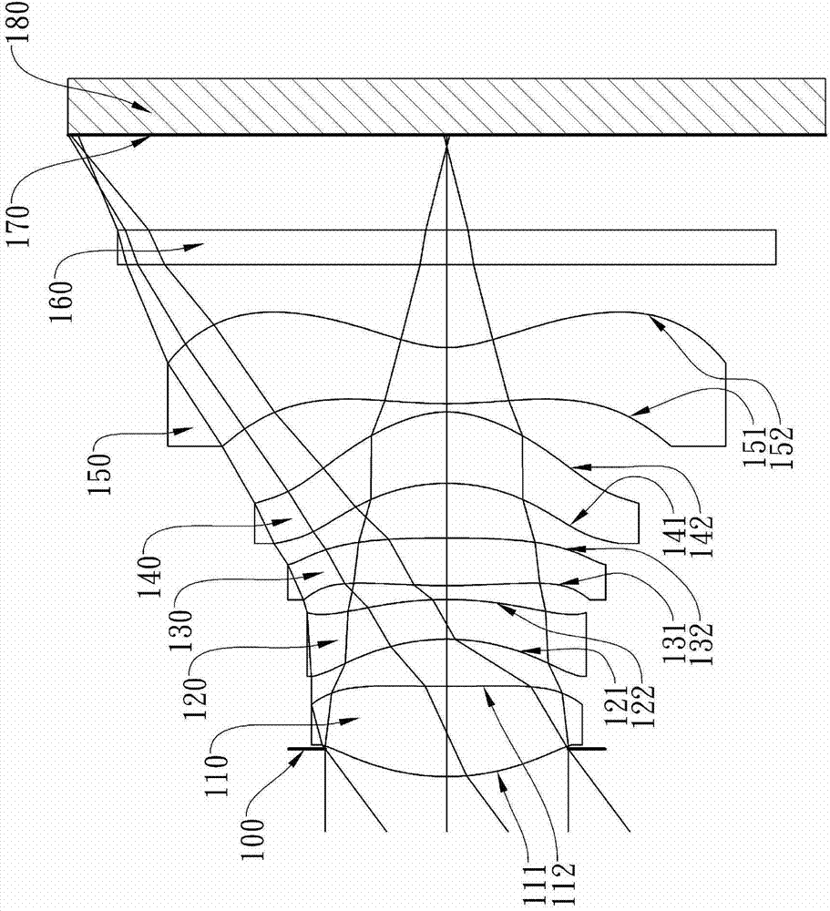
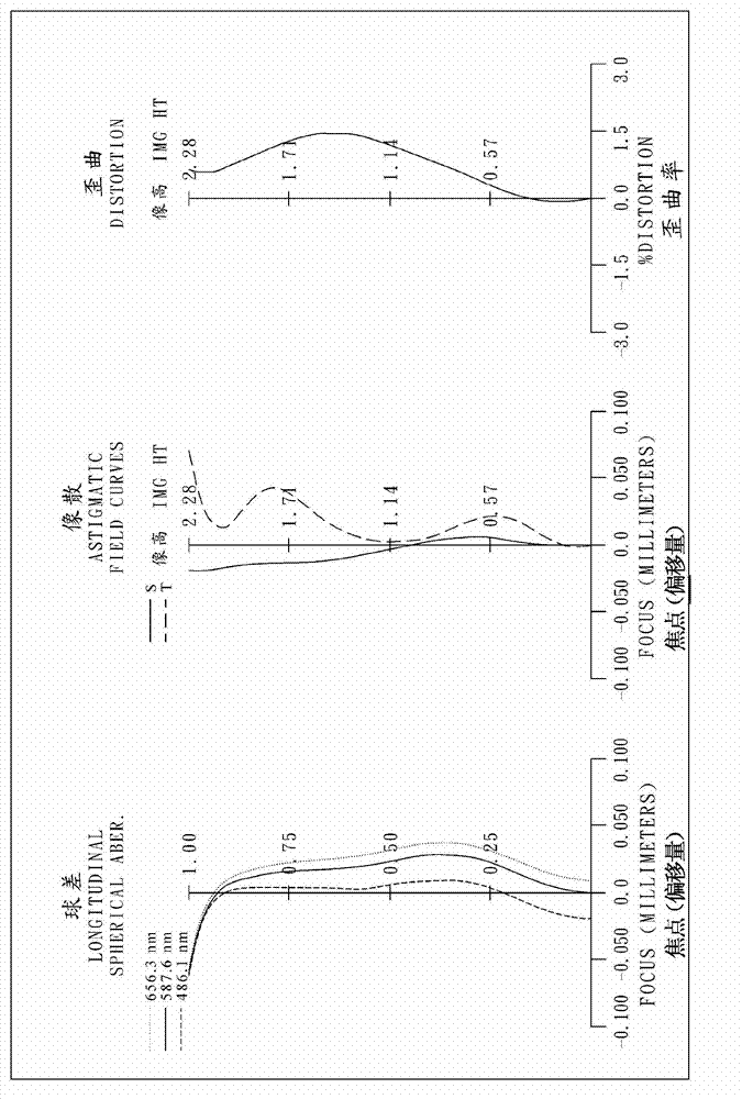
[0111] Please refer to the first embodiment of the present invention Figure 1A , for the aberration curve of the first embodiment, please refer to Figure 1B . The image capture system group of the first embodiment is mainly composed of five lenses with refractive power, which sequentially include from the object side to the image side:

[0112] A first lens (110) with positive refractive power, its object side (111) is convex and image side (112) is concave, its material is plastic, the object side (111) and image of the first lens (110) The side surfaces (112) are all aspherical surfaces;

[0113] A second lens (120) with negative refractive power, its object side (121) is concave and image side (122) is convex, its material is plastic, the object side (121) and image of the second lens (120) The side surfaces (122) are all aspherical surfaces;

[0114] A third lens (130) with positive refractive power, its object side (131) is convex and its image side (132) is convex, ...

no. 2 example 》

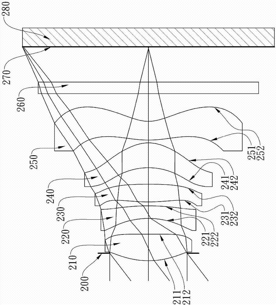
[0146] Please refer to the second embodiment of the present invention Figure 2A , for the aberration curve of the second embodiment, please refer to Figure 2B . The image capture system group of the second embodiment is mainly composed of five lenses with refractive power, which sequentially include from the object side to the image side:

[0147] A first lens (210) with positive refractive power, its object side (211) is convex and image side (212) is concave, its material is plastic, the object side (211) and image of the first lens (210) The side surfaces (212) are all aspheric surfaces;

[0148] A second lens (220) with negative refractive power, its object side (221) is concave and image side (222) is convex, its material is plastic, the object side (221) and image of the second lens (220) The side surfaces (222) are all aspheric surfaces;

[0149] A third lens (230) with positive refractive power, its object side (231) is convex and its image side (232) is convex, ...

no. 3 example 》

[0160] Please refer to the third embodiment of the present invention Figure 3A , for the aberration curve of the third embodiment, please refer to Figure 3B . The image capture system group of the third embodiment is mainly composed of five lenses with refractive power, which sequentially include from the object side to the image side:

[0161] A first lens (310) with positive refractive power, its object side (311) is convex and image side (312) is concave, its material is plastic, the object side (311) and image of the first lens (310) The side surfaces (312) are all aspherical surfaces;

[0162] A second lens (320) with negative refractive power, its object side (321) is concave and image side (322) is convex, its material is plastic, the object side (321) and image of the second lens (320) The side surfaces (322) are all aspheric surfaces;

[0163] A third lens (330) with positive refractive power, its object side (331) is convex and image side (332) is concave, its ...


PUM


Abstract

This invention provides an image capturing lens system comprising: a positive first lens element having a convex object-side surface; a negative second lens element having a concave object-side surface and a convex image-side surface; a third lens element with refractive power; a positive fourth lens element having a convex image-side surface, both of the object-side and image-side surfaces being aspheric; a fifth lens element with refractive power having a concave image-side surface, both of the object-side and image-side surfaces being aspheric, at least one inflection point is positioned on the image-side surface thereof. When some particular relations are satisfied, the light-focusing spots of various wavelengths can be favorably adjusted for extending the depth of field; therefore, the present image capturing lens system shall be suitable for compact electronic products with Extended Depth of Field (EDOF) function.

Description

technical field [0001] The present invention relates to an image capture system set, in particular to an image capture system set applied to miniaturized electronic products. Background technique [0002] In recent years, with the rise of portable electronic products with photography functions, the demand for optical systems has increased day by day. The photosensitive elements commonly used in general optical systems are nothing more than two types of photosensitive coupling devices (Charge Coupled Device, CCD) or complementary metal oxide semiconductor sensors (Complementary Metal-Oxide Semiconductor Sensor, CMOS Sensor). The size of the pixel is reduced, and the optical system is gradually developing into the high-pixel field. Users' requirements for image quality are also increasing day by day. [0003] The currently developed five-piece optical system, as disclosed in US Patent No. 8,000,030, does not have a good function of expanding the depth of field, so it is diff...

Claims


Application Information

Patent Timeline
Patent Type & Authority Applications(China)
IPC IPC(8): G02B13/00G02B13/18G02B1/04
CPCG02B13/0045
Inventor 廖凌峣黄歆璇
Owner LARGAN PRECISION
Why Eureka
Try Eureka