
Electronic device

A technology for electronic equipment and partitions, applied in the field of electronic equipment that is conducive to heat dissipation, can solve problems such as affecting the heat dissipation of expansion cards and less air volume, and achieve the effect of improving heat dissipation and increasing air flow.

Inactive Publication Date: 2014-02-19
HONG FU JIN PRECISION IND (SHENZHEN) CO LTD +1
View PDF4 Cites 1 Cited by
  • Summary
  • Abstract
  • Description
  • Claims
  • Application Information

AI Technical Summary

Problems solved by technology

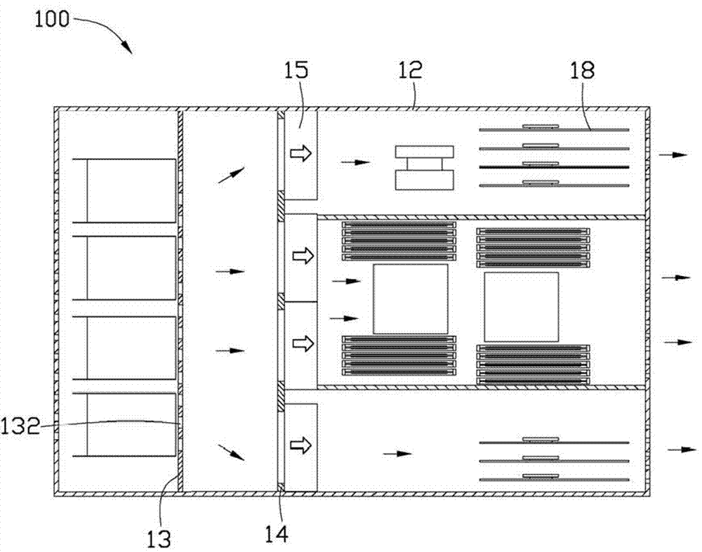
The fan 15 far away from these ventilation holes 132 sucks in less air volume, thereby affecting the heat dissipation of the expansion card 18

Method used


Image

  • Electronic device
  • Electronic device
  • Electronic device

Examples


Embodiment Construction

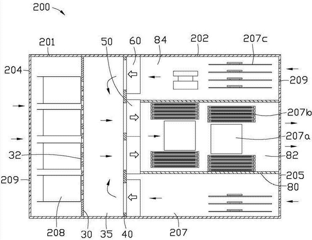
[0015] see image 3 A preferred embodiment of the electronic device 200 of the present invention includes a casing 201, and the casing 201 includes two opposite side walls 202, a first end wall 204 and a second end wall 205 opposite, a circuit board 207 and Several hard disks 208 . A central processing unit 207a and a plurality of memory sticks 207b are arranged in the middle of the circuit board 207 , and a plurality of expansion cards 207c are respectively arranged on two sides of the circuit board 207 . The first end wall 204 and the second end wall 205 respectively define a plurality of ventilation holes 209 . In this embodiment, the electronic device 200 is a server.

[0016] The electronic device 200 also includes a first partition 30 and a second partition 40 spaced apart and parallel to the first end wall 204 and the second end wall 205, a plurality of first fans 50, a plurality of second fans 60 and a vertically arranged The air guide cover 80 between the second pa...


PUM


Abstract

An electronic device comprises a shell. The shell comprises two opposite side walls, a first end wall and a second end wall, wherein the first end wall and the second end wall are opposite. A first partition and a second partition are arranged between the first end wall and the second end wall at intervals, a plurality of first fans are fixed to the middle of the second partition, a plurality of second fans are fixed to two ends of the second partition, air flow generated by the first fans and the second fans is opposite in direction, the first end wall, the first partition and the second end wall are respectively provided with a plurality of vent holes, the first fans lead the air flow into the space between the first partition and the second partition from the vent holes of the first end wall and the first partition and lead out the air flow from the vent holes in the middle of the second end wall through the second partition, and the second fans lead the air flow into the space between the first partition and the second partition from the vent holes in two ends of the second end wall. As the air flow generated by the first fans and the second fans of the electronic device is opposite in direction, the air flow generated by the first fans and the second fans within unit time is increased, and the radiating effect of the electronic device is improved.

Description

technical field [0001] The invention relates to an electronic device, in particular to an electronic device that is beneficial to heat dissipation. Background technique [0002] Usually, a heat dissipation device is provided to dissipate heat from the expansion card of the electronic device. [0003] Such as figure 1 As shown, an electronic device 100 includes a square casing 12, a first partition 13 and a second partition 14 arranged in parallel and oppositely in the casing 12, fixed side by side on the second partition 14 15 on the fan. A plurality of expansion cards 18 are disposed at a corner of the casing 12 along a direction perpendicular to the second partition 14 . A central portion of the first partition 13 defines a plurality of ventilation holes 132 along its extending direction, and the fan 15 introduces air into the ventilation holes 132 and blows it toward the expansion card 186 . The fans 15 far away from these ventilation holes 132 suck in less air volume...

Claims


Application Information

Patent Timeline
Patent Type & Authority Applications(China)
IPC IPC(8): G06F1/20
Inventor 黄文宏
Owner HONG FU JIN PRECISION IND (SHENZHEN) CO LTD
Learn More