Portable electronic devices and methods for positioning antennas of such devices

An electronic device and portable technology, applied in antennas, folded antennas, antenna arrays, etc., can solve problems such as changes in antenna performance, and achieve the effect of improving signal performance

Inactive Publication Date: 2014-02-19
HTC CORP
View PDF7 Cites 3 Cited by
  • Summary
  • Abstract
  • Description
  • Claims
  • Application Information

AI Technical Summary

Problems solved by technology

With such a configuration, the performance of the antenna may be changed by different factors such as the way the user holds the electronic device

Method used


Image

  • Portable electronic devices and methods for positioning antennas of such devices
  • Portable electronic devices and methods for positioning antennas of such devices
  • Portable electronic devices and methods for positioning antennas of such devices

Examples


Embodiment Construction

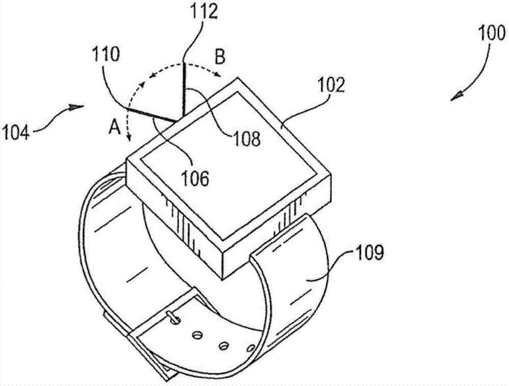
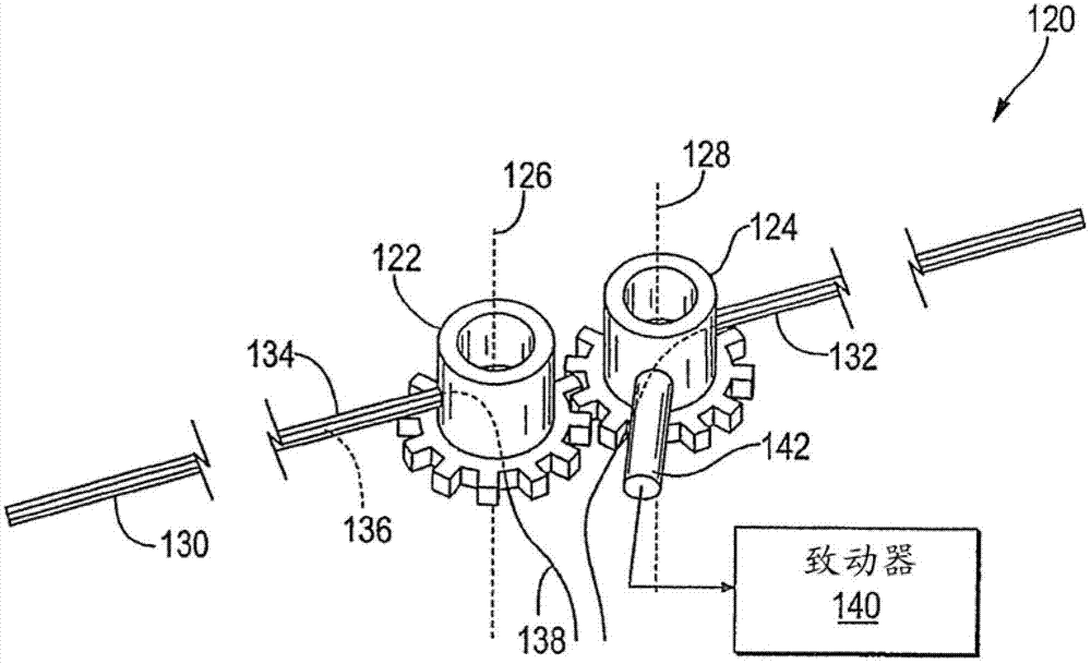
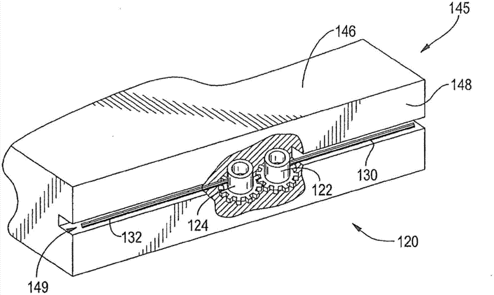
[0041] The invention provides a portable electronic device and a method for positioning an antenna of the portable electronic device. In an embodiment of the present invention, such a portable electronic device has a pair of antennas, and the antennas are configured to pivot on opposite rotation axes. For example, these antennas are elongated and extend radially from the axis so that the distal end of the antenna moves along a corresponding arc. In the embodiment of the present invention, the antennas move symmetrically, so that the movement of one of the antennas is reflected on the movement of the other of the antennas. It is worth noting that such a movement can be performed for one or more different purposes, such as improving the signal performance of the antenna.

[0042] figure 1 It is a schematic diagram of a portable electronic device according to an embodiment of the invention. Such as figure 1 As shown, the portable electronic device 100 includes a housing 102 and an...


PUM


Abstract

A representative device includes: a housing; and an antenna assembly mounted to the housing, the antenna assembly having a first antenna and a second antenna, the first antenna and the second antenna being movable between respective stowed and extended positions; in the stowed positions, the first antenna and the second antenna being positioned substantially within an outer periphery defined by the housing.

Description

Technical field [0001] The present invention relates to an electronic device, and more particularly to an electronic device with an antenna. Background technique [0002] Portable electronic devices, such as tablet computers and smart phones, include antennas used to facilitate communication. In particular, the antennas of such electronic devices are usually fixed in position. For example, the antenna may be located in the internal cavity of the electronic device and surrounded by the housing of the electronic device, and the housing forms the external housing of the electronic device. With this configuration, the performance of the antenna may be changed by different factors such as the way the user holds the electronic device. Summary of the invention [0003] The object of the present invention is to provide a portable electronic device and a method for positioning an antenna of the portable electronic device. [0004] To achieve the above objective, the present invention prov...

Claims


Application Information

Patent Timeline
Patent Type & Authority Applications(China)
IPC IPC(8): H01Q3/02H01Q1/22H01Q21/00
CPCH01Q1/084H01Q1/103H01Q1/1257H01Q1/273H01Q3/06
Inventor 罗德尼.O.威廉斯
Owner HTC CORP
Why Eureka
Try Eureka