Recursive demodulation apparatus and method

a demodulation apparatus and recursive technology, applied in the field of recursive demodulation apparatus and methods, can solve the problems of significant residual frequency/phase error, inability to accurately perform synchronization in a poor communication environment, and increase the error rate of detecting a signal based on a hard decision, so as to improve the performance of signal demodulation and improve the synchronization performan

Inactive Publication Date: 2010-12-02
ELECTRONICS & TELECOMM RES INST
View PDF3 Cites 3 Cited by
  • Summary
  • Abstract
  • Description
  • Claims
  • Application Information

AI Technical Summary

Benefits of technology

[0010]The present invention provides a recursive demodulation apparatus and method which may improve a performance of a signal demodulation even when a residual frequency / phase error significantly remains, and enable a receiving system to use a simple frequency / phase synchronization method, as opposed to a complex synchronization method to improve a synchronization performance.

Problems solved by technology

However, synchronization may not be accurately performed in a poor communication environment such as an environment with a low signal to noise ratio (SNR), although it depends on a synchronization method.
Accordingly, a residual frequency / phase error significantly remains.
Due to the residual frequency / phase error, a signal outside of a signal mapping grid section where a signal is to be mapped may occur, and thus an error rate when detecting a signal based on a hard decision may increase.
Accordingly, a storage device to store all symbols is required, detection may be delayed until an end of burst is processed, and transmission efficiency may decrease.
However, in the technology described above, a low SNR may cause error propagation, and thus performance may be significantly deteriorated.

Method used


Image

  • Recursive demodulation apparatus and method
  • Recursive demodulation apparatus and method
  • Recursive demodulation apparatus and method

Examples


Embodiment Construction

[0022]Hereinafter, embodiments of the present invention are described in detail by referring to the figures.

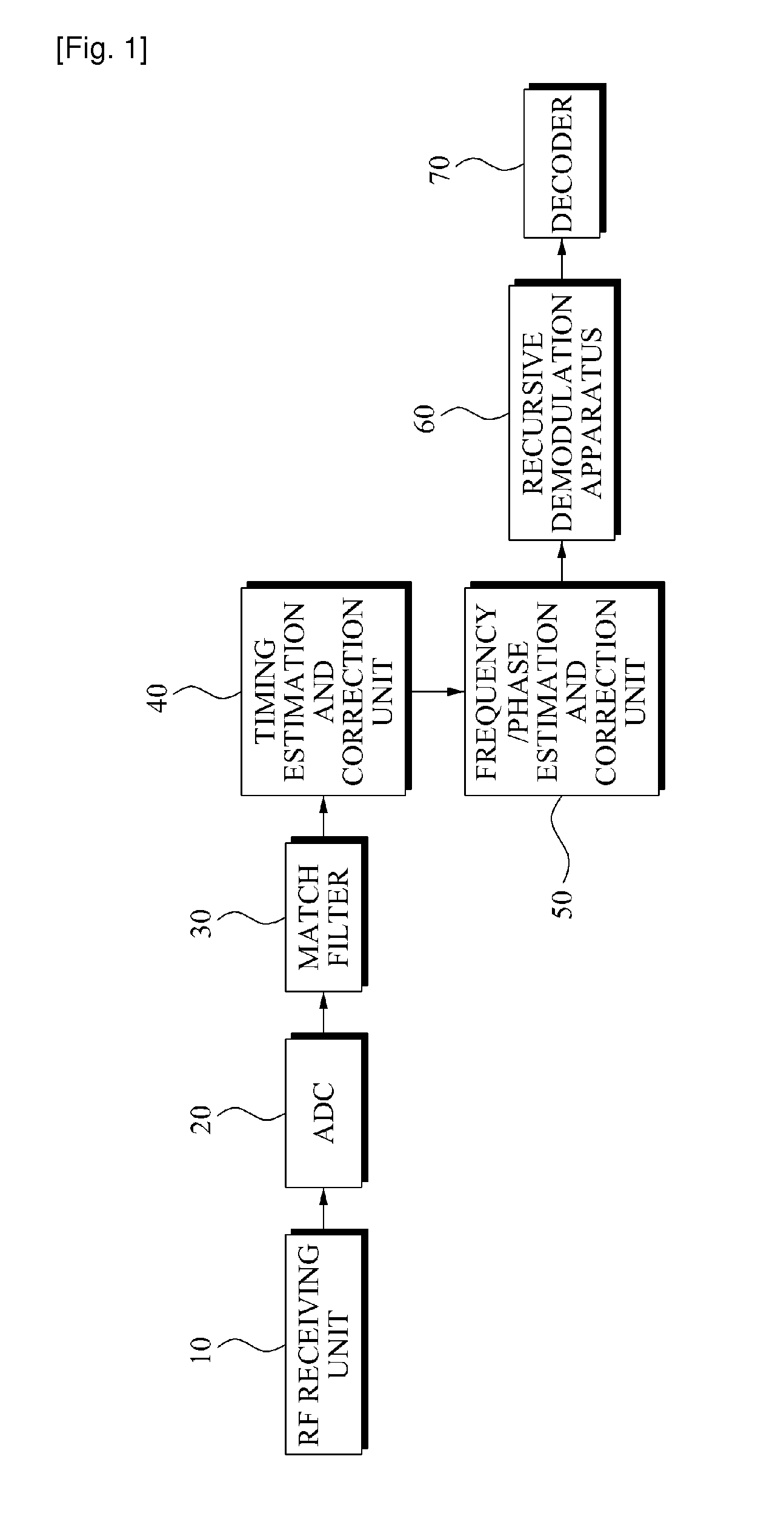
[0023]FIG. 1 is a block diagram illustrating an example of a receiving system including a recursive demodulation apparatus according to an embodiment of the present invention.

[0024]Referring to FIG. 1, the example of the receiving system including the recursive demodulation apparatus 60 includes a radio frequency (RF) receiving unit 10, analog to digital converter (ADC) 20, match filter 30, timing estimation and correction unit 40, frequency / phase estimation and correction unit 50, recursive demodulation apparatus 60, and decoder 70.

[0025]The receiving system has a configuration of an All Digital Feed-forward receiving system.

[0026]The RF receiving unit 10 receives and tunes an RF signal of a desired band, and downconverts the RF signal to a baseband.

[0027]The ADC 20 performs sampling with respect to an analog signal outputted from the RF receiving unit 10 at every predetermin...


PUM


Abstract

A recursive demodulation apparatus is provided. Therecursive demodulation apparatus, including: a segment generation unit dividing data symbols with a residual frequency or phase error into a predetermined number of data symbols, and generating a plurality of segments, each of the plurality of segments including the predetermined number of data symbols; and a phase error correction unit sequentially correcting a phase error of each of the data symbols, included in the each of the plurality of segments, for each segment.

Description

TECHNICAL FIELD[0001]The present invention relates to a recursive demodulation apparatus and method which efficiently corrects a residual frequency / phase error when the residual frequency / phase error exists after a synchronization of a receiving system in a burst mode digital communication.[0002]This work was supported by the IT R&D program of MIC / IITA. [2006-S-019-02, The development of digital cable transmission and receive system for 1 Gbps downstream]BACKGROUND ART[0003]In a burst transmission, a short preamble is attached and transmitted at a beginning of burst transmission, and a receiving unit performs a timing synchronization, frequency synchronization, phase synchronization, and the like for each burst using the short preamble to detect a signal.[0004]However, synchronization may not be accurately performed in a poor communication environment such as an environment with a low signal to noise ratio (SNR), although it depends on a synchronization method. Accordingly, a residu...

Claims


Application Information

Patent Timeline
Patent Type & Authority Applications(United States)
IPC IPC(8): H03D3/00
CPCH04L27/38H04L2027/0067H04L2027/0046H04L2027/003H03D3/00
Inventor HAHM, YOUNG KWONJIN, EUN SOOKSONG, YUN JEONGLEE, SOO IN
Owner ELECTRONICS & TELECOMM RES INST
Why Eureka
Try Eureka