Endoscope cutting stapler with stapler anvil capable of moving and rotating up and down

A stapler and anvil technology, applied in the field of laparoscopic cutting staplers, can solve problems such as damage to instrument parts, affecting surgical quality, and increasing operational resistance

Inactive Publication Date: 2014-03-05
徐维华
View PDF13 Cites 4 Cited by
  • Summary
  • Abstract
  • Description
  • Claims
  • Application Information

AI Technical Summary

Problems solved by technology

[0007] When the existing laparoscopic cutting stapler performs clamping of the anastomotic tissue to be cut, due to the pivot connection between the staple cartridge assembly and the staple anvil assembly, the staple anvil assembly cannot move up and down relative to the staple cartridge assembly at the pivot connection, so the tool When the beam moves back and forth in the execution head to perform the actions of clamping, anastomosis, cutting and reset, the staple cartridge assembly and the nail anvil assembly between the I-beam and the pivot are difficult to elastically deform in the up and down direction, and the I-beam and the pivot The tissue that has been cut and anastomotic is still clamped between the anvil and the staple cartridge, which forms a great resistance to the I-beam moving back and forth in the execution head, which will greatly increase the operation resistance, and even cause damage to the instrument parts. If the damage is caused, it cannot work normally, and it needs to be converted from laparoscopic surgery to open surgery, which will increase surgical trauma, prolong the operation time, and affect the quality of surgery

Method used


Image

  • Endoscope cutting stapler with stapler anvil capable of moving and rotating up and down
  • Endoscope cutting stapler with stapler anvil capable of moving and rotating up and down
  • Endoscope cutting stapler with stapler anvil capable of moving and rotating up and down

Examples


Embodiment Construction

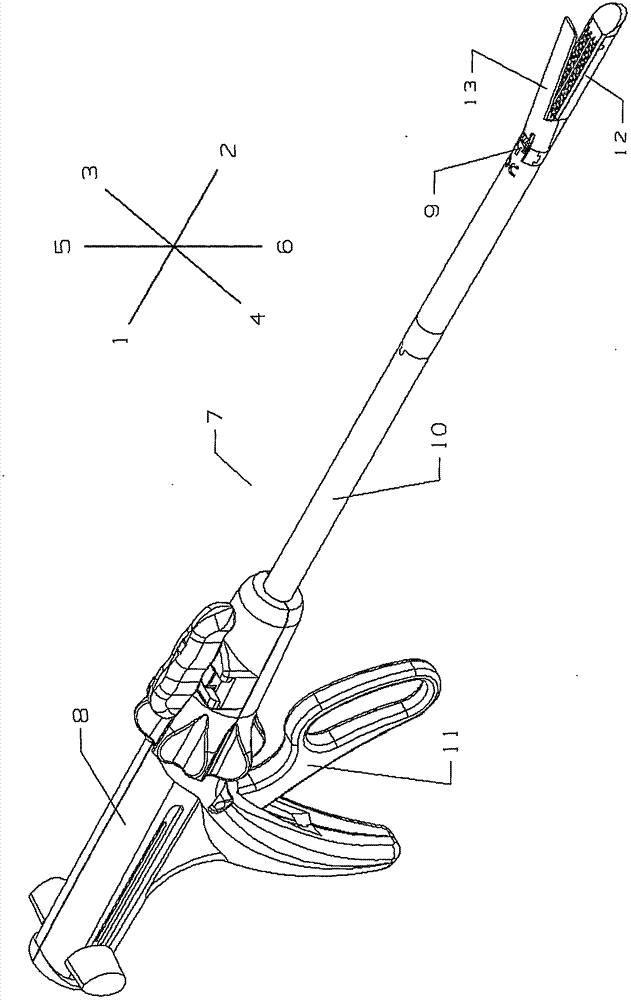
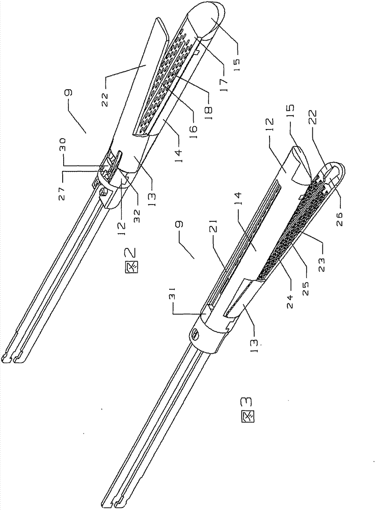
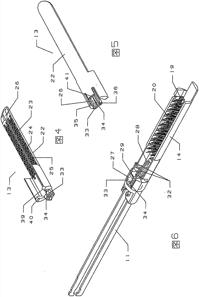
[0075] By way of example, the best embodiment of the endoscopic cutting stapler that the nail anvil of the present invention can move up and down and rotate is set forth below in conjunction with the accompanying drawings. The scope of the invention will be indicated in the claims. It should be recognized that some or all of the drawings are illustrative diagrams illustrating preferred embodiments of the invention and do not depict the true dimensions of the parts shown. The practical manner in which these and other objects and advantages of the invention are achieved will become more clearly understood by reference to the detailed description of the preferred embodiment.

[0076] In order to highlight the figure of the elastic collar and its description, except for the execution head of the laparoscopic cutting stapler, other components are not introduced in detail in the drawings. For the structure, installation, use and action process of other parts of various laparoscopic...


PUM


Abstract

The invention discloses an endoscope cutting stapler with a stapler anvil capable of moving and rotating up and down. The technical characteristics that an executing head is provided with constraint protruded blocks and constraint sliding grooves in the upper direction and the lower direction, and the constraint protruded blocks are installed in the constraint sliding grooves. Springs are installed in a stapler cartridge assembly, one end of each spring is pressed on the stapler anvil, and action force of the springs enables the stapler anvil to tend to move in the direction approaching a stapler cartridge are achieved. Therefore, under the constraint of the constraint protruded blocks and the constraint sliding grooves, the tissue contact surface of the stapler anvil can move and rotate up and down relative to the tissue contact surface of the stapler cartridge, and the executing head, where a puncture outfit with the 12mm caliber can be inserted, of the endoscope cutting stapler can be adopted to reach the technical effect that an original executing head of the endoscope cutting stapler can perform clamping, cutting and anastomosis on thick tissues with the need for inserting a puncture outfit with the 15mm caliber.

Description

technical field [0001] The present invention relates to a laparoscopic cutting stapler used in laparoscopic surgery, in particular to a laparoscopic cutting stapler used in laparoscopic surgery, and in particular to a laparoscopic cutting staple used in thoracoscopic surgery A stapler, more particularly relates to a laparoscopic cutting stapler with an anvil that can move up and down and rotate. Background technique [0002] In laparoscopic surgery and thoracoscopic surgery, various manual and electric endoscopic cutting staplers are usually used in the esophagus, stomach, duodenum, small intestine, colon, rectum, appendix, gallbladder, pancreas, etc. It is also used in cutting and anastomotic operations such as the lung and trachea in the respiratory tract, as well as the bladder and uterus in the urogenital system, which can reduce surgical trauma, shorten operation time, and improve operation quality. [0003] Existing laparoscopic cutting staplers include various laparo...

Claims


Application Information

Patent Timeline
Patent Type & Authority Applications(China)
IPC IPC(8): A61B17/072
CPCA61B17/07207A61B17/320016A61B2017/00818
Inventor 徐维华
Owner 徐维华
Why Eureka
Try Eureka