Window blind rotation sub-mechanism and timing control slider system comprising same

A shutter and slider technology, applied in the direction of windows/doors, building components, building structures, etc., can solve the problems of limited rotation angle, the outer diameter of the roll cannot be reduced, and the shape of the top rail of the shutter is bloated. Motion control for sophisticated and compact effects

Active Publication Date: 2014-03-05
HANGZHOU WOKASOLAR TECH
View PDF11 Cites 7 Cited by
  • Summary
  • Abstract
  • Description
  • Claims
  • Application Information

AI Technical Summary

Problems solved by technology

However, since the reel must ensure the number of turns of the hoisting rope, the outer diameter of the reel cannot be reduced. As a result, the shape of the top rail of the fixed-pitch blinds on which the reel is installed is bloated
The Chinese invention patent whose publication number is CN102839909A further improves the Chinese invention patent whose publication number is CN101818616A, and proposes the concept of variable-pitch shutters. The reel mechanism and reel system related to this variable-pitch louver are disclosed. The publication number is CN102839907A. The Chinese invention patent application discloses a slider mechanism and a slider system related to this variable-pitch louver. These mechanisms and systems are equipped with turning cylinders. , the rotation angle of the tumbler is limited by the structure, so the outer diameter of the tumbler cannot be reduced, which has the same defect as the roller of the fixed-pitch shutter

Method used


Image

  • Window blind rotation sub-mechanism and timing control slider system comprising same
  • Window blind rotation sub-mechanism and timing control slider system comprising same
  • Window blind rotation sub-mechanism and timing control slider system comprising same

Examples


Embodiment 1

[0065] Such as image 3As shown, a blind turning sub-mechanism includes a shell formed by fastening a base 38 and a top cover 39. The shell is longitudinally penetrated by the hexagonal prism-shaped main driving shaft 2 of the blind. The gear clutch 34, the front cable slider 361 of the ladder belt, the front and rear cable slider drive screw 363, and the rear cable slider 362 of the ladder belt through which the shaft 2 penetrates. The hollow front and rear cable slider drive screw 363 is in transmission connection with the gear clutch 34. The slider driving screw 363 is provided with two threaded sections with opposite helical directions, and a short smooth axial surface is arranged between the two threaded sections, and the near gear clutch end of the front and rear cable slider driving screw 363 is provided with a round tenon . The front cable slider 361 of the ladder belt and the rear cable slider 362 of the ladder belt are respectively threaded on the two thread segment...

Embodiment 2

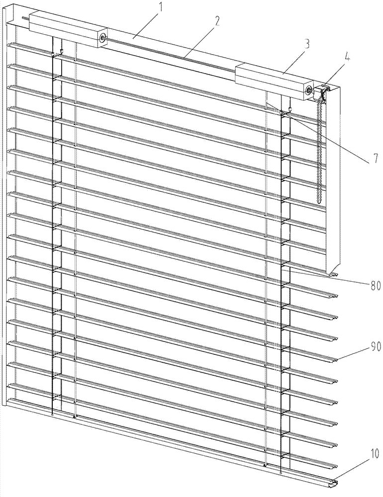
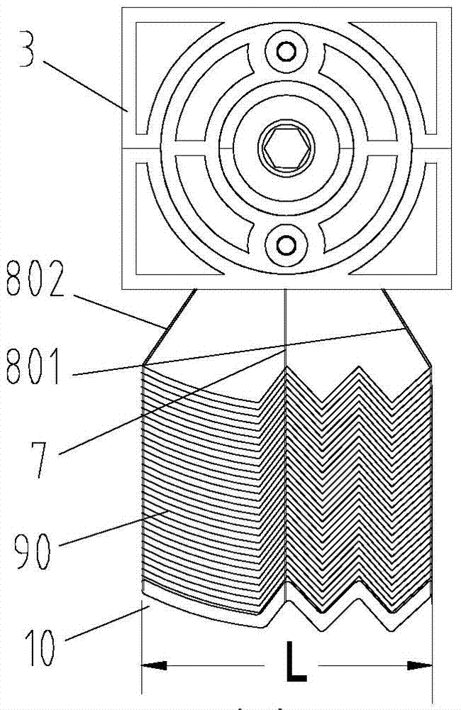
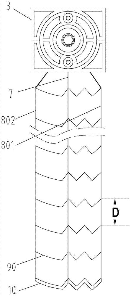
[0070] A time-sequence control slider system including the louver turning sub-mechanism of the present invention is used to control the overall retraction and the turning of the louver blades of the fixed-pitch louver. figure 1 It shows the three-dimensional diagram of the fixed-pitch shutter when it is unfolded. The fixed-pitch shutter is composed of the top rail 1, the shutter transmission mechanism, the lifting rope 7, the main ladder belt 80, the shutter blades 90 and the bottom rail 10. The shutter transmission mechanism is composed of a hexagonal column The total drive shaft 2, the slider system 3 and the driver 4 are composed, Figure 2 shows the cross-sectional view of the fixed pitch shutter in three states, Figure 2a A cross-sectional view of fixed pitch shutter louvers 90 raised and folded is shown, Figure 2b shows a cross-sectional view of the fixed-pitch shutter louvers 90 lowered and unfolded, Figure 2c Shows the cross-sectional view of the fixed-pitch louv...

Embodiment 3

[0075] A time-sequence control slider system 3 including the louver turning sub-mechanism of the present invention is used to control the overall retraction and the turning of the louver blades of the three-time quarter-variable-pitch louver. Figure 16 It shows the three-dimensional diagram when the three-time four-point variable-pitch shutter is unfolded. The three-time four-point variable-pitch shutter is composed of a top rail 1, a shutter transmission mechanism, a lifting rope 7, a main ladder belt 80, a second ladder belt 81, and a second ladder belt 82. The second third ladder belt 83, the main louver blade 90, the second 100 blade 91, the second 200 blade 92, the second 300 blade 93 and the bottom rail 10; System 3 and driver 4 are composed.

[0076] Figure 17 shows a schematic diagram of the unit-combined louver cross-section of the three-time quarter-variable pitch louver, where only the main louver 90, the second 100th blade 91, the second 200th louver 92, and the s...


PUM


Abstract

The invention discloses a window blind rotation sub-mechanism comprising a housing formed by fastening a base and a top cover together. The housing is penetrated by a master drive shaft of a window blind. The base is provided with a gear clutch, a ladder tape front cable slider, a front and rear cable slider drive screw and a ladder tape rear cable slider, which are all penetrated by the master drive shaft in order. The front and rear cable slider drive screw which is hollow is in transmission connection with the gear clutch. The front and rear cable slider drive screw is provided with two thread segments having opposite spiral directions. The ladder tape front cable slider and the ladder tape rear cable slider are connected to the two thread segments of the front and rear cable slider drive screw respectively in a threaded manner. The invention further discloses a timing control slider system comprising the window blind rotation sub-mechanism. The assembly of the sliders and screw replaces the traditional reel or rotating drum to allow slats of a fixed pitch or variable pitch window blind to rotate, the radial size can be reduced greatly, and the window blind rotation sub-mechanism and even whole motion control process are more ingenious and compact.

Description

technical field [0001] The invention relates to a shutter movement control mechanism, more specifically, it relates to a shutter turning mechanism and a timing control slide block system using the mechanism. Background technique [0002] The flipping of the louvers of the blinds has always been achieved by the rotation of the roller or the turning cylinder. At present, the transmission mechanism of the fixed-pitch blinds is driven by a hexagonal shaft, two or more rollers with two annular grooves, and a The hexagonal shaft passes through more than two reels and the drive box, and the hexagonal shaft can be rotated by pulling the bead chain or rotating the rocker or pressing the remote control to drive the reel rotate. The upper end of the lifting rope is fixed on the reel in an annular groove on the reel, the lower end of the lifting rope is connected to the bottom rail of the blind, and the two upper ends of the ladder belt are wrapped around the reel in another annular gr...

Claims


Application Information

Patent Timeline
Patent Type & Authority Applications(China)
IPC IPC(8): E06B9/32E06B9/322
CPCE06B9/386E06B9/303E06B9/322
Inventor 张一飞武成尚许辉文
Owner HANGZHOU WOKASOLAR TECH
Why Eureka
Try Eureka