Novel lock pin device

A new type of locking pin technology, which is applied in the direction of connecting components, quick-action fasteners, mechanical equipment, etc., can solve the problems of complex connection and release of parts, and achieve the effect of reliable work and flexible operation

Inactive Publication Date: 2014-03-05
中国船舶重工集团公司第七〇五研究所
View PDF5 Cites 6 Cited by
  • Summary
  • Abstract
  • Description
  • Claims
  • Application Information

AI Technical Summary

Problems solved by technology

The existing connection methods between parts often use fixed connection methods such as screws, pins, and keys. The connection and release between parts are relatively complicated, and it is often necessary to disassemble the parts as a whole before performing the corresponding connection or release operation.

Method used


Image

  • Novel lock pin device
  • Novel lock pin device
  • Novel lock pin device

Examples


Embodiment Construction

[0017] Describe the present invention below in conjunction with specific embodiment:

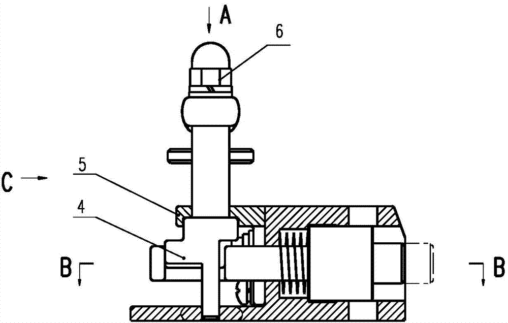
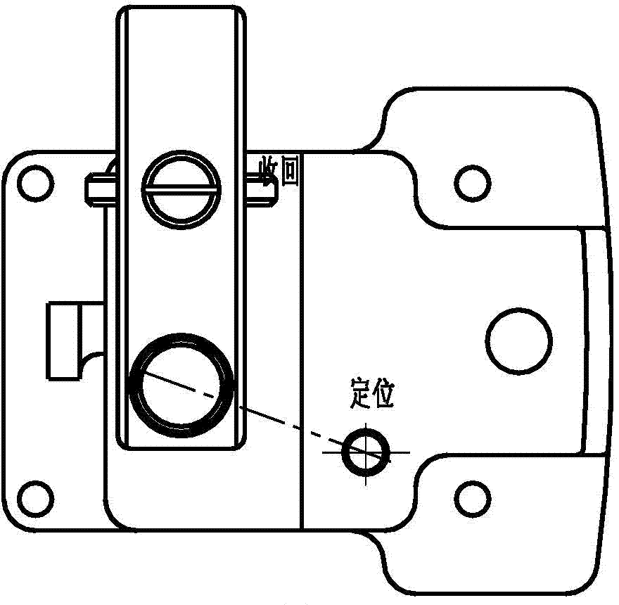
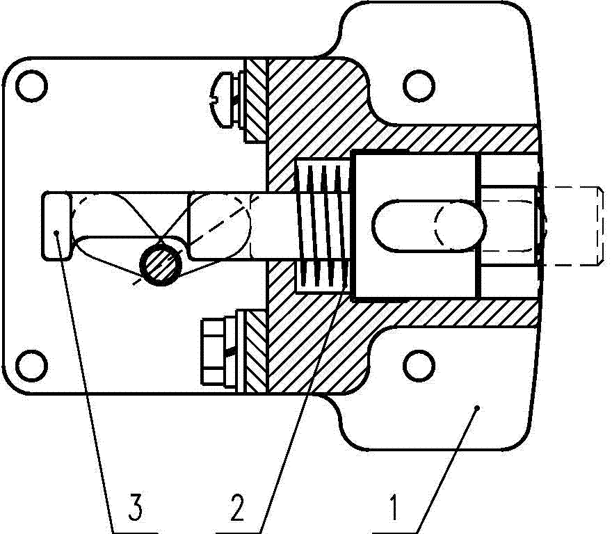
[0018] Refer to attached figure 1 to attach Figure 4 , A novel locking device of the present invention includes a locking pin seat 1 , a locking pin 3 , a rotating shaft 4 , a locking pin handle 8 and a positioning pin 10 .

[0019] The lock pin seat has a step through hole for accommodating the lock pin, and the lock pin cover 5 is fixed on the lock pin seat by screw pins 11 . The locking pin 3 passes through the locking pin cover 5 and is installed in the stepped through hole of the locking pin seat. Refer to attached Image 6 , the locking pin is divided into a driving section, a shaft shoulder section and a locking pin section in the axial direction, wherein a groove is opened on the driving section, the shaft shoulder section is inside the locking pin seat, and a compression spring 2 is sleeved on the shaft shoulder section, and the compression spring 2. The two ends are against th...


PUM


Abstract

The invention discloses a novel lock pin device. The novel lock pin device comprises a lock pin base, a lock pin, a rotary shaft, a lock pin handle and a positioning pin. The lock pin is axially divided into a driving section, a shaft shoulder section and a lock pin section, wherein a groove is formed in the driving section. The two ends of a compression spring abut against the wall faces of a shaft shoulder and the lock pin base. A cambered-surface protrusion is arranged at the end portion of the rotary shaft, and the protrusion is arranged in the groove of the driving section of the lock pin. When the rotary shaft rotates, the protrusion can push the two side faces of the groove to drive the lock pin to move axially. The lock pin handle is fixedly connected with the rotary shaft. The positioning pin is arranged in the middle of the lock pin handle, and the two ends of a positioning spring abut against an annular protrusion and a stepped face of a stepped through hole. According to the novel lock pin device, due to the fact that the cambered-face protrusion of the rotary shaft drives the lock pin to stretch or retract axially and the lock pin is sleeved with the compression spring, the axial bumping motion of the lock pin is prevented; due to the fact that the lock pin handle is positioned by the positioning pin, the connection and disconnection of the two parts are achieved, limiting structures are both arranged at the connection position and the disconnection position, operation is flexible, no clamping phenomenon exists, and the working of the novel lock pin device is reliable.

Description

technical field [0001] The invention relates to a novel lock pin device, which can conveniently perform the connection and release operations between two components. Background technique [0002] The locking pin device is used for connection and release between two parts. The existing connection methods between parts often adopt fixed connection methods such as screws, pins, and keys. The connection and release between parts are relatively complicated, and it is often necessary to disassemble the parts as a whole before performing the corresponding connection or release operation. Contents of the invention [0003] technical problem to be solved [0004] In order to solve the problems existing in the prior art, the present invention proposes a new lock pin device, through the rotary motion of the lock pin handle, the lock pin is advanced or retreated along its axial direction, so as to realize the connection and release between the two parts. Both release and connection ...

Claims


Application Information

Patent Timeline
Patent Type & Authority Applications(China)
IPC IPC(8): F16B21/04F16B21/08
Inventor 邵卫赵雄辉孙铁绳汤伟江高卓
Owner 中国船舶重工集团公司第七〇五研究所
Why Eureka
Try Eureka