Grain weighing device

A weighing device and grain technology, which is applied in the direction of measuring device, weighing, automatic feeding/discharging weighing equipment, etc., can solve the problems of low work efficiency and achieve low labor intensity, simple structure and convenient operation Effect

Inactive Publication Date: 2014-03-05
大连金马衡器有限公司
0 Cites 2 Cited by

AI-Extracted Technical Summary

Problems solved by technology

If the hopper is directly used to discharge the material, the we...

Abstract

The invention discloses a grain weighing device. The grain weighing device comprises a granary, a discharge port is arranged below the granary, a weighing hopper is arranged below the discharge port and connected with a weighing device body, the weighing hopper is of an axisymmetric structure as a whole, the symmetry axis is in the horizontal direction, the left and the right of the weighing hopper are respectively provided with a round side plate, three baffles are arranged between the two side plates, a material separating hopper is formed by every two adjacent baffles, the left side plate and the right plate in an enclosing mode, a horizontal shaft hole is formed in the center of the weighting hopper, a rotary shaft passes through the shaft hole, the lower portions of the two ends of the rotary shaft are respectively supported by a sensor, and the sensors are connected to a digital processing device and a displayer. Through rotation of the weighing hopper, the weighing work for the next batch can be carried out when the last batch of materials are discharged, and thus the grain weighing device is high in weighing efficiency, simple in structure and convenient to operate and further reduces labor intensity of workers.

Application Domain

Weighing apparatus with automatic feed/discharge

Technology Topic

Image

  • Grain weighing device
  • Grain weighing device

Examples

  • Experimental program(1)

Example Embodiment

[0010] The present invention will be further described below in conjunction with accompanying drawing.
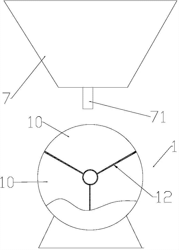
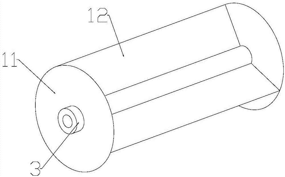
[0011] In the grain weighing device of the present invention, a discharge port is provided below the grain storage bin 7, and the discharge port 71 discharges the grain into the weighing bucket 1, and the weighing bucket 1 has an axisymmetric structure as a whole, and the axis of symmetry is in the horizontal direction. 1 There is a circular side plate 11 on the left and right, and three baffles 12 are arranged between the two side plates 11. The adjacent two baffles 12 and the left and right side plates 11 form a distribution hopper, and the center of the weighing bucket 1 is set A horizontal shaft hole through which the rotating shaft passes. Bearings are provided at both ends of the rotating shaft, and a sensor is supported below it. The sensor is connected to a digital processing device and a display to measure the weight change of the hopper. The weighing hopper 1 can rotate along the rotating shaft. When the grain in the weighing hopper 1 reaches the set value, turn the weighing hopper 1, and the grain in the sub-hopper can be discharged with the rotation, and the other sub-hopper comes under the discharge port at the same time. , you can continue to weigh.
[0012] In order to facilitate the rotation of the weighing bucket 1, a pulley 3 coaxial with the circular side plate 11 is installed, and the pulley is driven by an electric motor. When the electric motor fails to work, the weighing bucket 1 can also be manually rotated temporarily. For the convenience of manual operation, the outer edge of the circular side plate 11 is provided with a layer of anti-skid belt, which is made of rubber material and has a pattern on the surface.

PUM

no PUM

Description & Claims & Application Information

We can also present the details of the Description, Claims and Application information to help users get a comprehensive understanding of the technical details of the patent, such as background art, summary of invention, brief description of drawings, description of embodiments, and other original content. On the other hand, users can also determine the specific scope of protection of the technology through the list of claims; as well as understand the changes in the life cycle of the technology with the presentation of the patent timeline. Login to view more.

Similar technology patents

Automatic pipe body weighing turnover frame

Owner:昆山圣源机械有限公司

Live pig weight measuring method based on deep learning and depth camera

PendingCN113706512AImprove weighing efficiencyReduce human interventionImage enhancementImage analysisImage analysisBody weight measure
Owner:INNER MONGOLIA UNIVERSITY

Classification and recommendation of technical efficacy words

  • Improve weighing efficiency
  • Simple structure

Powder ash material weighing system and weighing method

ActiveCN102680061AImprove weighing efficiencyWeighing apparatus with automatic feed/dischargeStart upMechanical engineering
Owner:SANY HEAVY IND CO LTD (CN)

Marine organism hazardous substance detection weighing device

ActiveCN106908125AImprove weighing efficiencyWeighing apparatus for materials with special property/formEngineeringHazardous substance
Owner:ZHEJIANG MARICULTURE RES INST

Beam expanding optical element, beam expansion method, image display apparatus, and head-mounted display

InactiveUS20070188837A1Reduce color unevennessSimple structureOptical light guidesSubstrate with hologramHead worn displayLight wave
Owner:KONICA MINOLTA INC

Microlithographic projection exposure apparatus

InactiveUS20050068499A1Simple structureReliable and low-maintenance operationProjectorsPhotomechanical exposure apparatusCamera lensPhysics
Owner:CARL ZEISS SMT GMBH
Why Eureka
Try Eureka