Supercharge Your Innovation With Domain-Expert AI Agents!

High speed dome monitor

A high-speed ball, monitor technology, applied in the direction of TV, color TV, closed-circuit TV system, etc., can solve the problems of unfavorable heat, unfavorable camera monitoring concealment, imaging chip imaging effect and easy exposure of service life, etc., to achieve good monitoring effect. , the effect of simple structure

Inactive Publication Date: 2014-03-05
CHENGDU JINGLIN ELECTRONICS TECH
View PDF4 Cites 1 Cited by
  • Summary
  • Abstract
  • Description
  • Claims
  • Application Information

AI Technical Summary

Problems solved by technology

[0004] The heat generated by the above-mentioned LED light group is not conducive to the imaging effect and service life of the imaging chip, and the light generated by the LED light group that rotates with the lens is also easy to expose the monitoring range of the camera at any time, which is not conducive to the concealment of camera monitoring. problem, the present invention provides a high-speed ball monitor

Method used


Image

  • High speed dome monitor

Examples


Embodiment 1

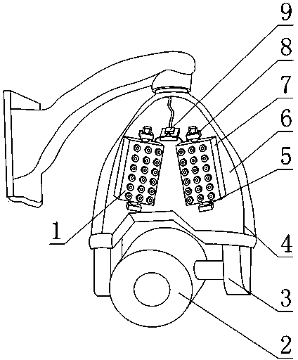
[0025] As shown in Figure 1, the high-speed dome monitor provided by the present invention includes a camera 2, a high-speed dome 3 and a casing 4, the high-speed dome 3 is partly located in the casing 4, the camera 2 is fixedly connected to the high-speed dome 3, and at least Two LED lamp groups 1, each LED lamp group 1 includes an LED lamp holder 7 and a plurality of LED lamps fixed on the LED lamp holder 7, and the housing 4 is also provided with a number equal to the number of LED lamp groups 1 Each LED lamp group 1 is installed on a LED lamp group installation station, and the angle between the LED lamp group 1 and the LED lamp group installation station is adjustable.

[0026] In the present invention, the high-speed ball 3 that is set is the pan-tilt system, which drives the camera 2 to rotate to realize monitoring in the range of 360°; The setting of the adjustable included angle of the installation station of the LED lamp group makes the irradiation position of the LE...

Embodiment 2

[0028] This embodiment is further limited on the basis of Embodiment 1, as shown in Figure 1, each LED lamp group installation station includes an upper connection block 8 provided with a through hole and a lower connection block 5 provided with a blind hole, each The sides of the LED lamp group 1 are provided with two columnar projections whose axes are collinear, one of which is arranged in the blind hole of the lower connection block 5 and fits in a gap with the blind hole, and the other projection is provided with an external thread , the other protrusion runs through the through hole of the upper connection block 8, and a locking nut is also arranged on the free end of the other protrusion.

[0029] This arrangement is simple in structure. The lower connection block 5 and the upper connection block 8 that cooperate with each LED lamp group 1 form a connection relationship with the LED lamp group 1. When the irradiation angle of the LED lamp group 1 meets the requirements, ...

Embodiment 3

[0031] This embodiment is further limited on the basis of Embodiment 1. As shown in FIG. 1 , the fixed connection surface between the LED lamp holder 7 and a plurality of LED lamps is a concave surface.

[0032] It also includes a photoresistor 9 and a power supply wire of the LED lamp, and the photoresistor 9 is connected in series on the power supply wire of the LED lamp.

[0033] It also includes a transparent baffle 6 , the LED lamp groups 1 are all arranged on the inner wall of the casing 4 , the transparent baffle 6 is fixedly connected to the casing 4 and is located directly in front of the LED lamp group 1 .

[0034] The setting of the fixed connection surface between the LED lamp holder 7 and the plurality of LED lamps is a concave surface to obtain a better light-focusing effect of the LED lamp group, which is conducive to long-distance fixed-point supplementary light convergence.

[0035] The set photoresistor 9 is used to control the on-off of the power supply wire...


PUM


Abstract

The invention discloses a high speed dome monitor. The high speed dome monitor comprises a camera, a high speed dome and a shell, wherein the high speed dome is partially located in the shell, and the camera is fixedly connected to the high speed dome. The high speed dome monitor further comprises at least two LED lamp banks, and each LED lamp bank comprises an LED lamp base and a plurality of LED lamps fixed to the LED lamp base. LED lamp bank mounting positions with the number equal to that of the LED lamp banks are further arranged on the shell, each LED lamp bank is mounted at one LED lamp bank mounting position, and the included angles between the LED lamp banks and the LED lamp bank mounting positions can be adjusted. According to the high speed dome monitor, heat generated by the LED lamp banks can be effectively prevented from affecting the imaging effect and the service life of an imaging chip of the camera, and key monitoring areas and dark areas can be compensated for light in a targeted mode; the design that the LED lamp banks and the camera are arranged in a split mode is favorable for interfering with the judgment about which area is monitored by the camera at any time made by people.

Description

technical field [0001] The invention relates to the field of high-speed dome cameras, in particular to a high-speed dome monitor. Background technique [0002] With the further development of the security industry, the high-speed dome camera has become the darling of the monitoring field due to its advantages of wide monitoring range, no blind spots, precise positioning, and fast tracking (the speed of the high-speed dome is above 120° / s). [0003] In existing high-speed dome cameras, LED light groups used for lens fill light are generally arranged around the lens, and the LED light groups rotate together with the lens. Although this setting is beneficial to the imaging effect of the lens, because the LED light group is close to the lens, the heat generated by the LED light group is not conducive to the imaging effect and service life of the imaging chip; the light generated by the LED light group that rotates with the lens is also It is easy to expose the monitoring range ...

Claims


Application Information

Patent Timeline
IPC IPC(8): H04N5/225H04N7/18F21V33/00F21Y101/02F21Y105/16F21Y115/10
Inventor 殷刚
Owner CHENGDU JINGLIN ELECTRONICS TECH
Features
  • R&D
  • Intellectual Property
  • Life Sciences
  • Materials
  • Tech Scout
  • Unparalleled Data Quality
  • Higher Quality Content
  • 60% Fewer Hallucinations
Learn More