Eureka AIR delivers breakthrough ideas for toughest innovation challenges, trusted by R&D personnel around the world.

Socket assembly

A composite and sleeve technology, applied in hand-held tools, wrenches, wrenches, etc., can solve the problems of lower structural strength of the sleeve, scratches on aluminum rings, inability to apply aluminum ring disassembly operations, etc., to save manufacturing costs , good strength effect

Active Publication Date: 2014-03-12
胡厚飞
View PDF4 Cites 3 Cited by
  • Summary
  • Abstract
  • Description
  • Claims
  • Application Information

AI Technical Summary

Problems solved by technology

[0002] It is quite unavoidable for the existing sleeve to collide with the aluminum ring when it is used for disassembly and assembly of the aluminum ring, and it is quite difficult to avoid scratches on the aluminum ring, especially when the sleeve is driven by a pneumatic wrench, the aluminum ring will be severely scratched due to vibration , this situation is quite disturbing but difficult for users to solve
[0003] Therefore, the sleeve currently used for the aluminum ring of an automobile can wrap a plastic sleeve with color around the outside of the sleeve, and use the plastic sleeve to prevent the sleeve from directly hitting the aluminum ring and use the color to mark the applicable size of the sleeve. However, the aluminum ring of the automobile The hole diameter of the bolt is smaller than the general specification, and it is impossible to use the general sleeve for disassembly and assembly operations. Therefore, the size of the existing sleeve is very demanding. However, the structural strength of the sleeve will decrease with the size of the sleeve. Maintaining a certain structural strength and strengthening the thickness of the sleeve will make it unsuitable for disassembly and assembly of aluminum rings
[0004] In view of the fact that the problems of the above-mentioned background technology cannot be effectively solved and overcome, the applicant proposes this patent application to solve the above-mentioned problems

Method used


Image

  • Socket assembly
  • Socket assembly
  • Socket assembly

Examples


Embodiment Construction

[0034] Regarding the technology, means and effects adopted by the present invention, three preferred embodiments are given and described in detail below with drawings, which are for illustration purposes only, and are not limited by this structure in the patent application.

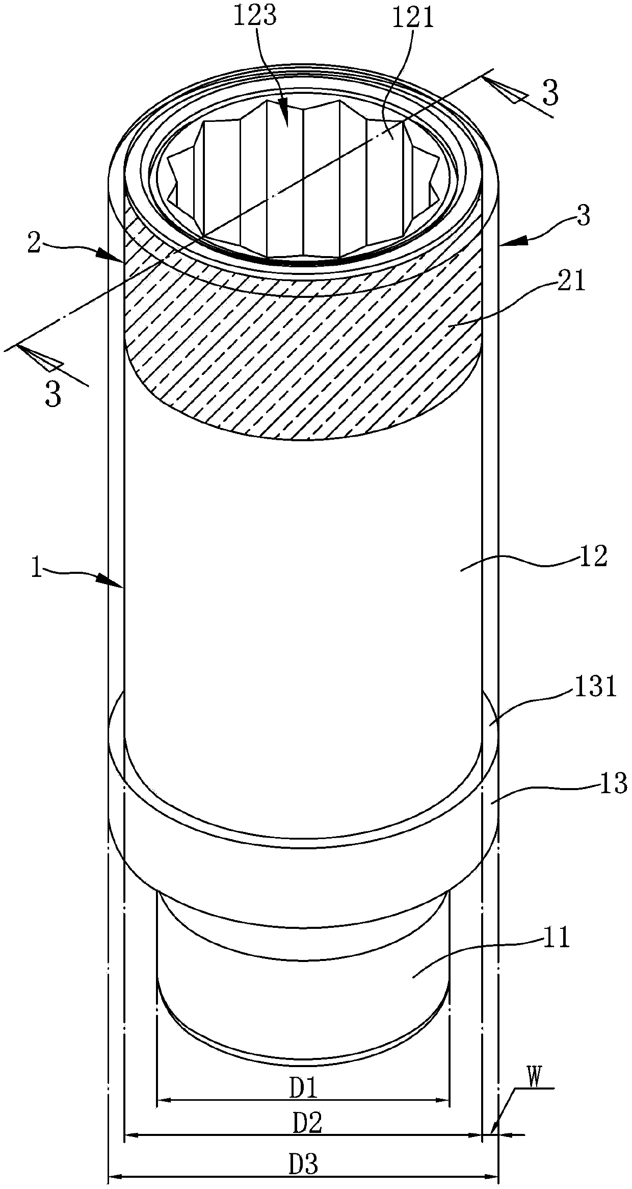
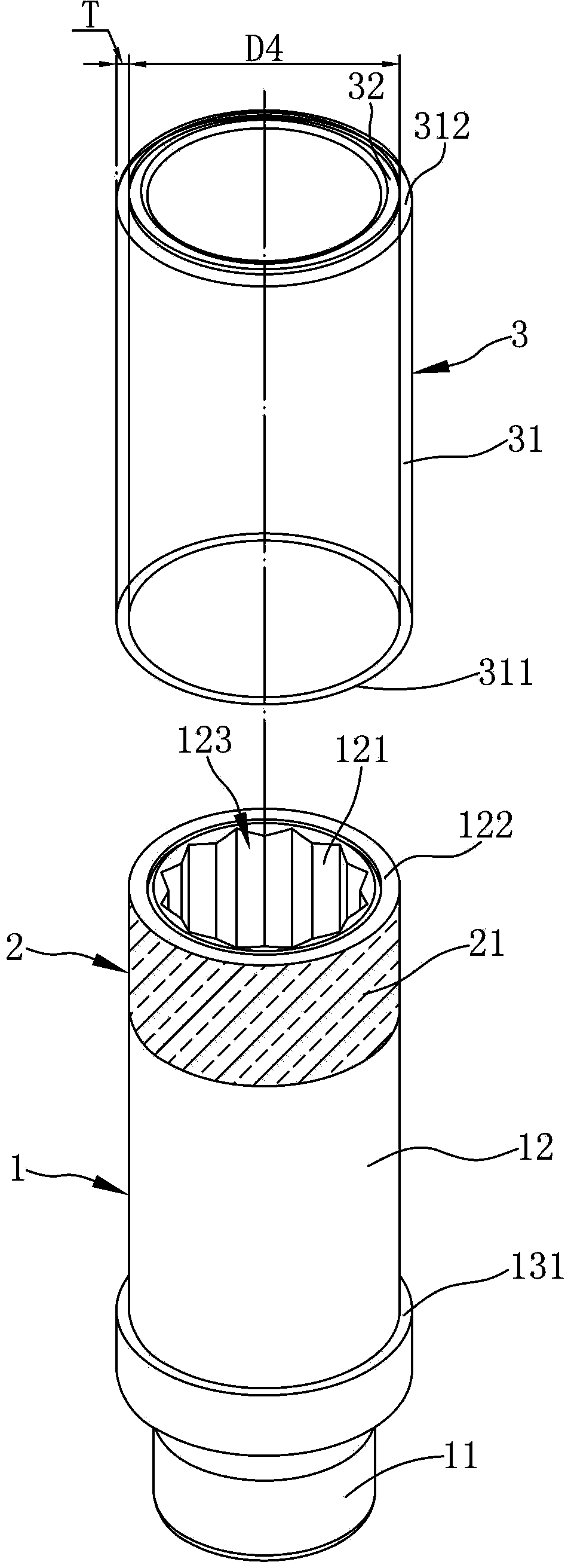
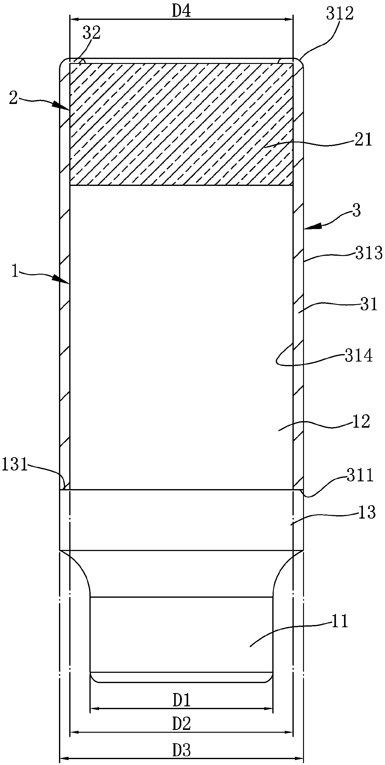
[0035] Please refer to Figure 1 to Figure 3 , is the three-dimensional appearance view, three-dimensional exploded view and cross-sectional view of the first embodiment of the composite sleeve of the present invention. The composite sleeve of the present invention can be respectively connected with a driving tool and a fixing part (not shown in the figure), the driving tool can be a wrench, an air tool, an electric tool or an automatic machine, and the fixing part can be a screw or a nut ...and other components of fixed objects. The sleeve includes a body 1, a socket 2 and a bushing 3; wherein, one end of the body 1 is connected to one end of the socket 2, and the bush 3 is sleeved between the body 1 an...


PUM


Abstract

A socket assembly includes a body having a driving portion to be driven by a driving tool and a transmission portion for driving a fastener. The transmission portion includes a first end and a second end spaced from the first end along a longitudinal axis. The first end of the transmission portion is connected to the driving portion. A sleeve is mounted around the second end of the transmission portion. A jacket is mounted around the transmission portion and the outer periphery of the sleeve. The transmission portion of the body and an outer periphery of the sleeve are visible through outer and inner peripheries of the jacket.

Description

technical field [0001] The invention relates to a sleeve, in particular to a special sleeve for aluminum rings. Background technique [0002] It is quite unavoidable that the existing sleeve will collide with the aluminum ring when it is used for disassembly and assembly of the aluminum ring of the car, and the aluminum ring will be scratched, especially when the sleeve is driven by a pneumatic wrench, the aluminum ring will be severely scratched due to vibration. , this situation is quite disturbing but difficult to solve for the user. [0003] Therefore, the sleeve currently used for automobile aluminum rings will wrap a colored plastic sleeve around the outside of the sleeve, and use the plastic sleeve to prevent the sleeve from directly hitting the aluminum ring and use the color to mark the applicable size of the sleeve. However, the automobile aluminum ring The hole diameter of the bolt is smaller than the general specification, and it is impossible to use the general...

Claims


Application Information

Patent Timeline
Patent Type & Authority Applications(China)
IPC IPC(8): B25B23/00B25B27/14
CPCB25B13/06B25B23/00B25B27/14
Inventor 胡厚飞
Owner 胡厚飞
Why Eureka
Eureka Blog
Learn More