Engineering maintenance vehicle traction force and brake force control method and system

A brake control and traction technology, applied in railway brake systems, brakes, etc., can solve problems such as uncoordinated brake coordination and personal safety of staff, and achieve the effect of smooth operation and coordinated execution actions

Active Publication Date: 2014-03-12
ZHUZHOU ELECTRIC LOCOMOTIVE CO LTD
View PDF4 Cites 17 Cited by
  • Summary
  • Abstract
  • Description
  • Claims
  • Application Information

AI Technical Summary

Problems solved by technology

[0003] In view of this, this application provides a method and system for controlling the traction force and braking force of an engineering maintenance vehicle, which is used to solve the problem that the braking coordination between the BCU and the TCU is not coordinated, which may easily cause the personal safety of the staff

Method used


Image

  • Engineering maintenance vehicle traction force and brake force control method and system
  • Engineering maintenance vehicle traction force and brake force control method and system
  • Engineering maintenance vehicle traction force and brake force control method and system

Examples


Embodiment 1

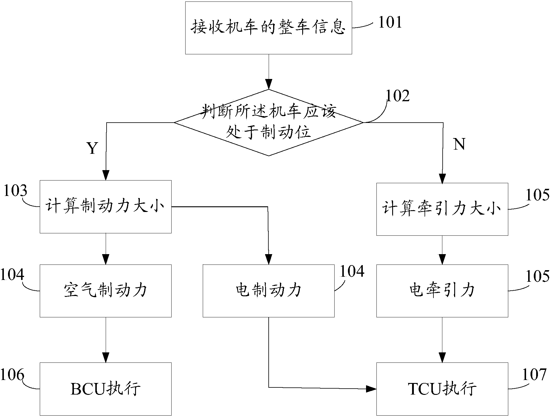
[0037] see figure 1 , figure 1 It is a flowchart of a control method for traction force and braking force of an engineering maintenance vehicle disclosed in the embodiment of the present application.

[0038] Such as figure 1 As shown, the method includes:

[0039] Step 101: receiving vehicle information of the vehicle;

[0040] Specifically, the whole vehicle information of the locomotive may include position information of the controller and real-time status information of the locomotive. For example, if the position of the controller is at the traction position or braking position, the real-time state information of the locomotive is: the switch state of the locomotive reserve circuit is closed, the state of the locomotive main break switch is closed, the locomotive is in power supply mode, the locomotive is in speed limit mode, Information such as the real-time traction exerted by the locomotive and the current real-time speed of the locomotive.

[0041] Step 102: Acc...

Embodiment 2

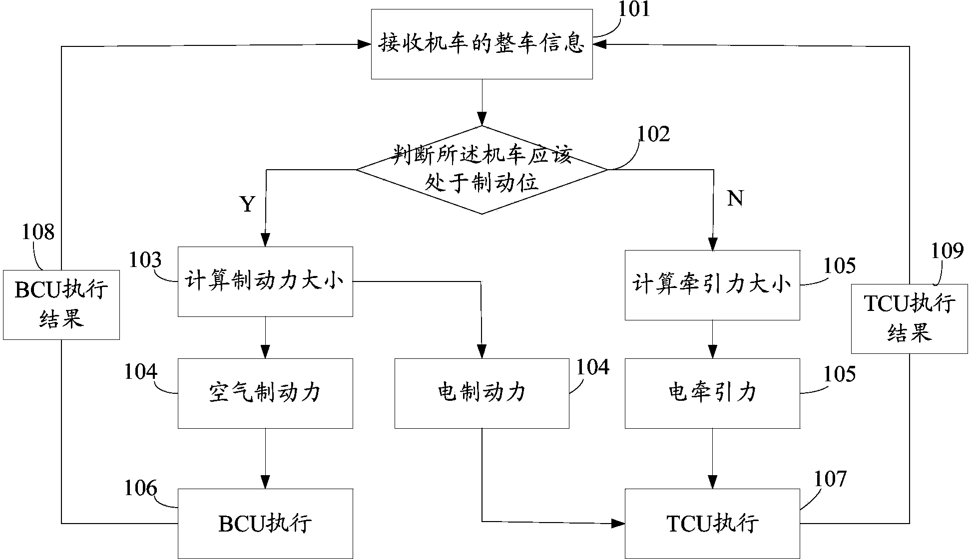
[0054] see figure 2 , figure 2 It is a flow chart of another control method for traction force and braking force of an engineering maintenance vehicle disclosed in the embodiment of this application.

[0055] Such as figure 2 As shown, on the basis of the first embodiment, this embodiment further adds step 108: receiving the execution result fed back by the BCU; and step 109: receiving the execution result fed back by the TCU.

[0056] Specifically, after the BCU and TCU execute the braking or traction action, the execution result is fed back to step 101, so that the whole vehicle information considered by the locomotive is more comprehensive.

Embodiment 3

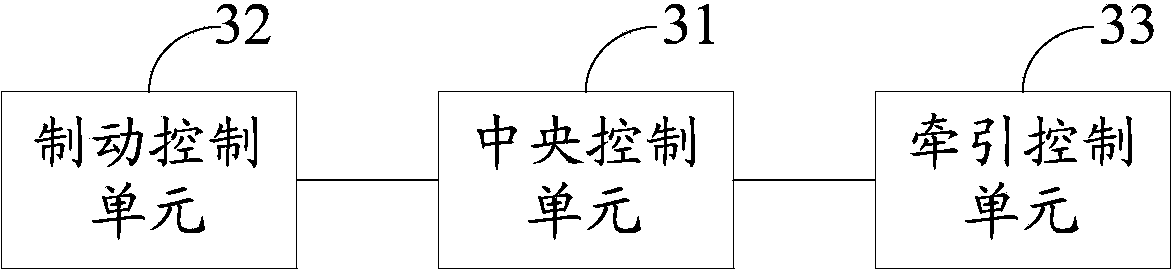
[0058] see image 3 , image 3 It is a composition diagram of a traction force and braking force control system of an engineering maintenance vehicle disclosed in the embodiment of this application.

[0059] Such as image 3 As shown, the system includes:

[0060] The central control unit 31 is used to receive the vehicle information of the locomotive, and judge whether the locomotive should be in the braking position, and if the judgment result is yes, calculate the braking force, and divide the braking force into air braking force and electric braking force, when the judgment result is negative, calculate the magnitude of the traction force;

[0061] A braking control unit 32, configured to execute an air braking action according to the air braking force generated by the central control unit;

[0062] The traction control unit 33 is configured to perform an electric braking action or an electric traction action according to the magnitude of the electric braking force or ...


PUM


Abstract

The invention discloses an engineering maintenance vehicle traction force and brake force control method, which comprises the following steps that the whole vehicle information of a locomotive is received; whether the locomotive is expected to be in the brake position or not is judged according to the whole vehicle information; under the condition that the judging result shows that the locomotive is expected to be in the brake position, the dimension of the brake force is calculated; the brake force is divided into air brake force and electric brake force, the air brake force and the electric brake force are respectively delivered to a BCU (brake control unit) and a TCU (traction control unit) for executing the brake action; under the condition that the judging result shows that the locomotive is not expected to be in the brake position, the dimension of the traction force is calculated; the traction force is delivered to the TCU for executing the traction action. The engineering maintenance vehicle traction force and brake force control method has the advantages that through the integral consideration on the integral vehicle information, the dimension of the traction force or the brake force required to be exerted by an engineering maintenance vehicle is obtained, and in addition, the traction force or the brake force is allocated, so the execution action of the TCU and the BCU is more coordinated, the operation of the engineering maintenance vehicle is more stable, more energy can be saved, and the safety is higher.

Description

technical field [0001] The present application relates to the technical field of locomotive control, and more specifically, relates to a method and system for controlling traction force and braking force of an engineering maintenance vehicle. Background technique [0002] The existing engineering maintenance vehicle controls the distribution between the electric traction force and the electric braking force through the traction control unit TCU (Traction Control Unit), and when the air brake is required, it is calculated by the brake control unit BCU (Brake Control Unit) The size of the air braking force. However, there is a lack of communication between the traction control unit TCU and the brake control unit BCU, and there will be a certain lack of coordination in the distribution of braking force between the TCU and the BCU. Moreover, the TCU receives relatively few vehicle signals, and cannot know all the current real-time information of the vehicle, so there will be a ...

Claims


Application Information

Patent Timeline
Patent Type & Authority Applications(China)
IPC IPC(8): B61H11/00B60T8/17
Inventor 颜罡李先岭秦庆民郭彦每李年锁皮凯俊
Owner ZHUZHOU ELECTRIC LOCOMOTIVE CO LTD
Why Eureka
Try Eureka