A brake command signal generator for driver controller

A technology of signal generating device and driver controller, applied in railway braking system, operating mechanism of railway vehicle brake, locomotive, etc., can solve the problem of rotary potentiometer overload and overheating, no protection, easy to burn out rotary potentiometer, etc. , to achieve the effect of improving service life and working reliability, and improving working conditions

Active Publication Date: 2016-03-02
扬中市冠捷科创有限公司
View PDF5 Cites 0 Cited by
  • Summary
  • Abstract
  • Description
  • Claims
  • Application Information

AI Technical Summary

Problems solved by technology

Although this method is simple, because the signal current required by the brake equipment of different locomotives as loads is different, the signal current required by the brake equipment under different operating conditions of the same locomotive is also different, the maximum can reach 1A, and the rotation often occurs. The potentiometer is damaged due to overload and overheating, which makes the brake fail
In addition, when the signal current required by the brake equipment is relatively small, the load effect of the brake equipment may not be considered. There is a certain linear relationship between the position of the control handle and the output voltage value of the rotary potentiometer. , at this time, the current output by the sliding tap of the rotary potentiometer is also large, so that the output voltage value becomes smaller, and the corresponding relationship between the position of the control handle and the output voltage value of the rotary potentiometer becomes more complicated, and there is a serious nonlinear relationship
Finally, without any protection, it is easy to burn out the rotary potentiometer when the load is shorted

Method used


Image

  • A brake command signal generator for driver controller
  • A brake command signal generator for driver controller
  • A brake command signal generator for driver controller

Examples


Embodiment Construction

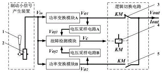
[0015] The present invention will be further explained below in conjunction with the accompanying drawings and specific embodiments. Such as figure 1 As shown, the present invention is composed of a braking small signal generating device, a power conversion module A, a power conversion module B, a voltage sampling circuit A, a voltage sampling circuit B, a fault detection module and a logic switching circuit. The output end of the braking small signal generating device is respectively connected to the input ends of the power conversion module A, the power conversion module B and the fault detection module, and the voltage sampling circuit A is connected in series between the power conversion module A and the fault detection module, and the power conversion module B and the fault detection module are connected in series. The voltage sampling circuit B is connected in series between the fault detection modules; the output ends of the power conversion module A, the power conversi...


PUM


Abstract

The invention discloses a braking command signal generating device of a driver controller. When both a first power conversion module and a second power conversion module work normally, the first power conversion module generates output voltage according to voltage input by a braking small signal generating device through a logic switching circuit, and the second power conversion module serves as a standby; a fault detection module monitors the voltage input by the braking small signal generating device and voltage output by two voltage sampling circuits on line, when the fault detection module detects that the first power conversion module breaks down, voltage is output so that a coil of a contactor can be powered on, a normally-closed contact of the contactor is switched off, a normally-opened contact is switched on, and the second power conversion module generates output voltage according to the voltage input by the braking small signal generating device through the logic switching circuit; power needed by braking equipment is provided by a power converter, and work conditions of a rotary potentiometer are improved; the dual-redundancy power converter is adopted for output, service life of the driver controller is prolonged, and work reliability of the driver controller is improved.

Description

technical field [0001] The present invention relates to a driver controller for controlling the running speed, direction and working condition of the locomotive on a rail vehicle, in particular to a braking command signal generating device for the driver controller, which is especially suitable for locomotives, urban subways, light rails and other fields . Background technique [0002] The driver controller is a master electrical appliance that is mainly used in locomotives, urban subways, light rails and other fields, and is operated by the driver to control the operation of the locomotive. The working performance of the driver controller directly affects the smooth operation of the locomotive and the realization of various operating conditions, and its small faults will bring great safety hazards to the locomotive, such as "stealing cars", electrical equipment receiving wrong instructions and causing malfunctions, etc. . The braking command signal generating device of th...

Claims


Application Information

Patent Timeline
Patent Type & Authority Patents(China)
IPC IPC(8): B61H13/02B61C17/04
Inventor 张新华骆浩朱建新赵文祥
Owner 扬中市冠捷科创有限公司
Why Eureka
Try Eureka