Automatic discharging device

A blanking device and automatic technology, applied in the direction of transportation and packaging, slideway, etc., can solve the problems of inconvenient retrieving and affecting the efficiency of insertion and insertion, and achieve the effect of avoiding chaos

Active Publication Date: 2014-03-12
GREE ELECTRIC APPLIANCES INC
View PDF9 Cites 8 Cited by
  • Summary
  • Abstract
  • Description
  • Claims
  • Application Information

AI Technical Summary

Problems solved by technology

[0003] The purpose of the present invention is to provide an automatic blanking device to solve the technical problems that it is inconvenient for employees to take materials and affect the insertion efficiency

Method used


Image

  • Automatic discharging device
  • Automatic discharging device
  • Automatic discharging device

Examples


Embodiment Construction

[0028] The embodiments of the present invention will be described in detail below with reference to the accompanying drawings, but the present invention can be implemented in many different ways defined and covered by the claims.

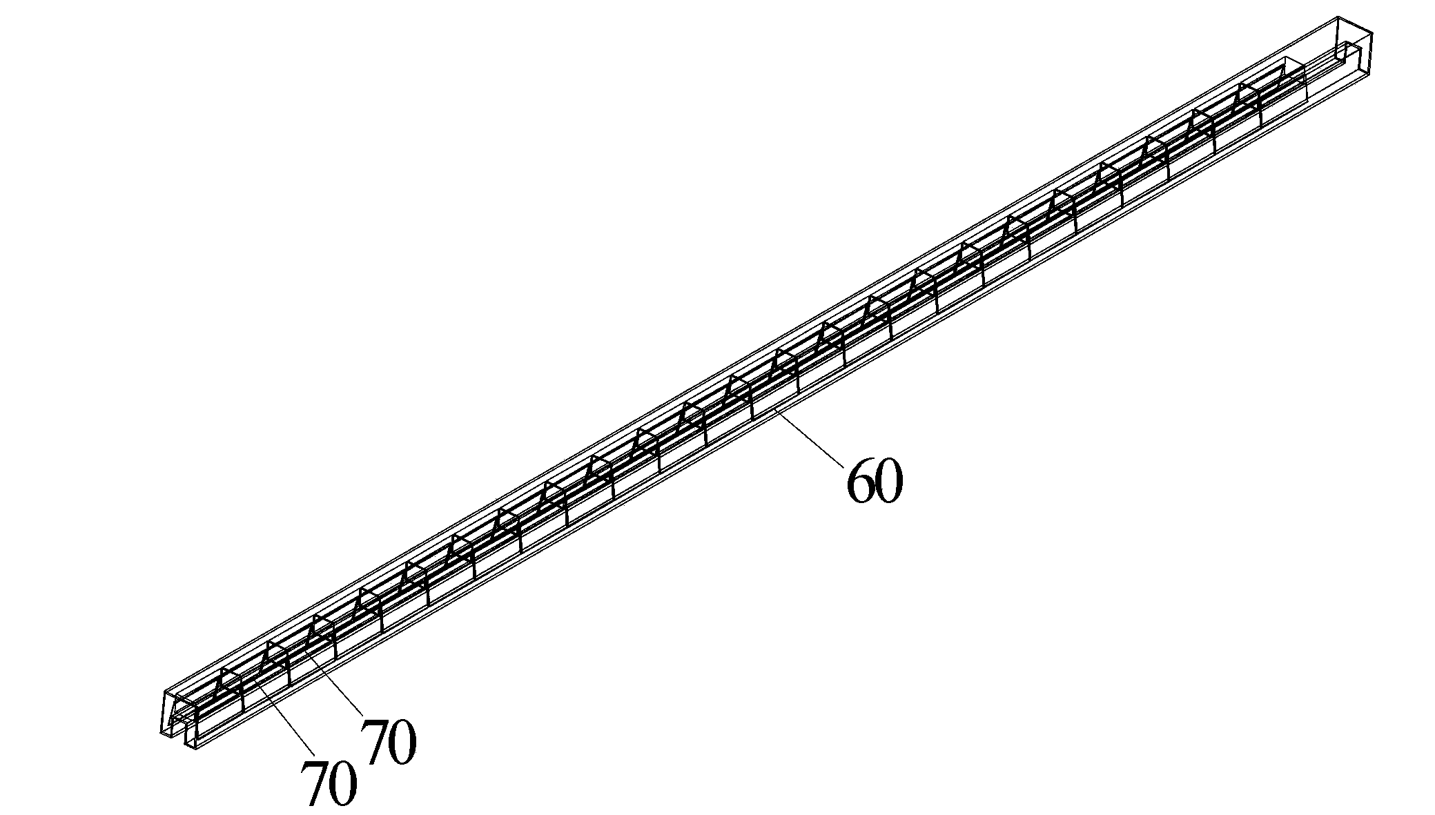
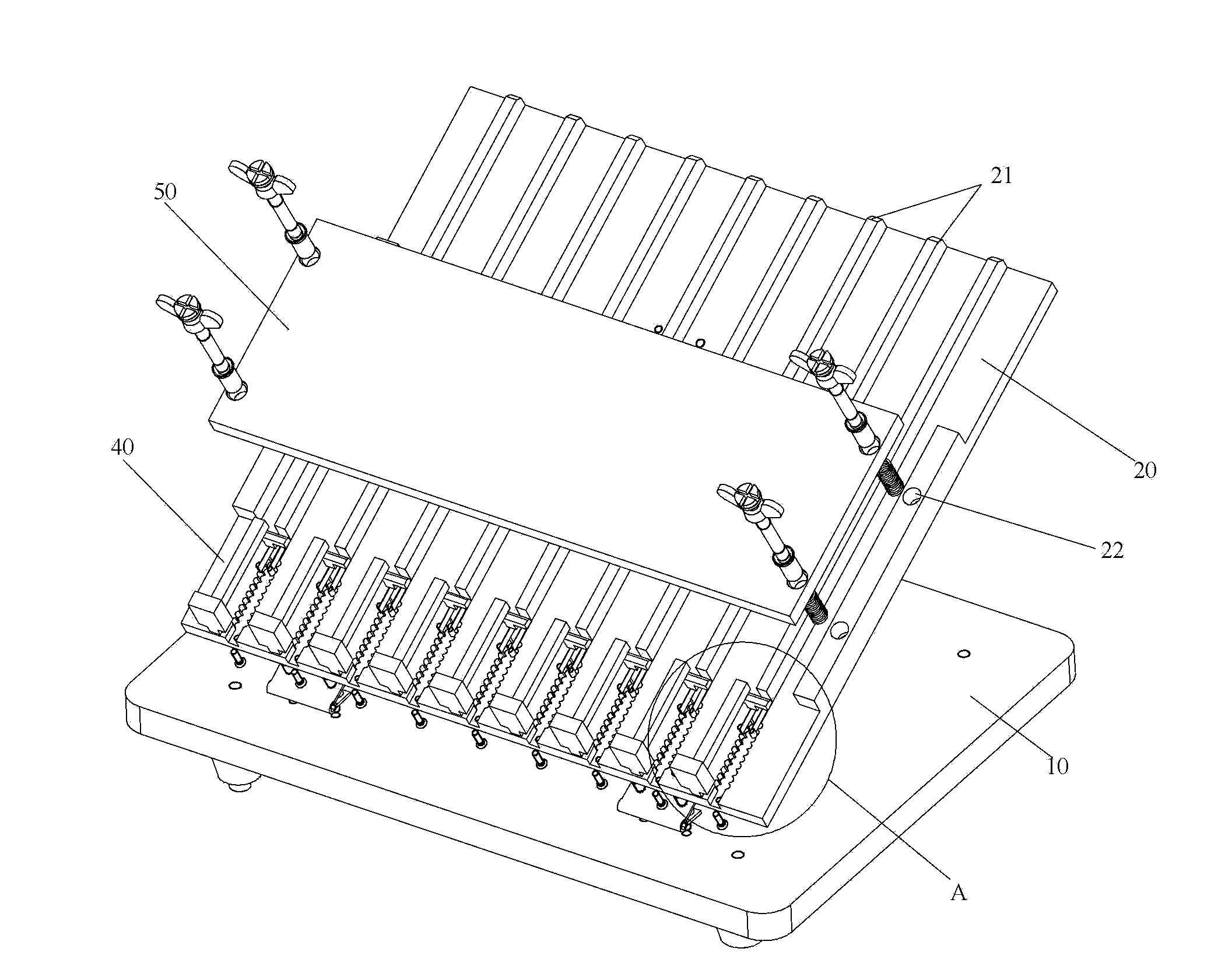
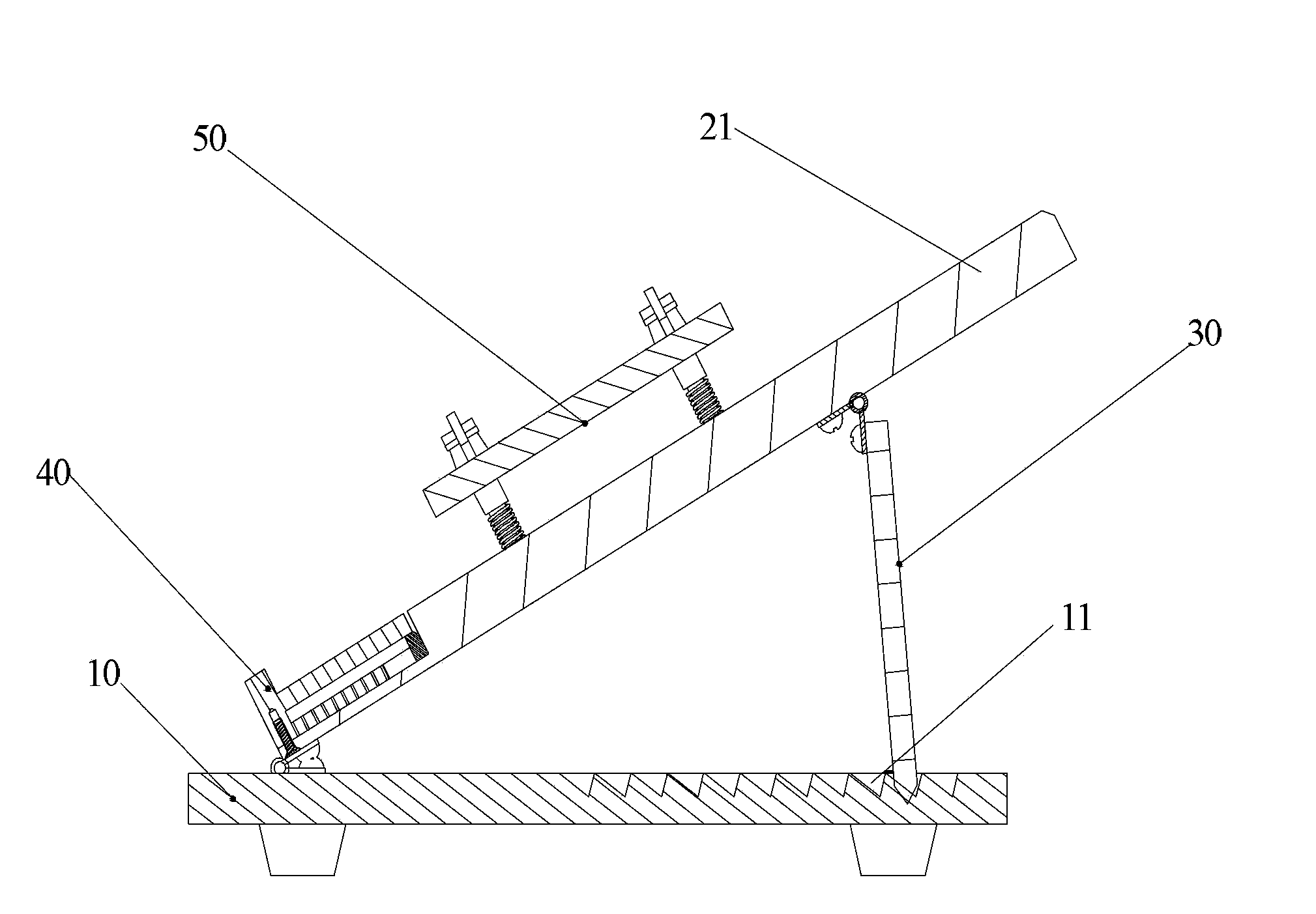
[0029] see Figure 2 to Figure 7 , according to a kind of automatic blanking device of the present invention, comprise blanking board 20, vertically or obliquely be arranged on the horizontal plane; Rail 21 is arranged on blanking board 20, material tube 60 is placed on track 21, and material tube The electronic components 70 in the 60 can slide down along the track 21 ; the main block 43 is arranged at the lower end of the track 21 , and is used to block the electronic components 70 on the track 21 in sequence. By setting the track, the material tube is fixed on the track 21, without the need for electronic components to be poured from the inside of the material tube into the material box, so that the current problems of mutual extrusion of electro...


PUM


Abstract

The invention provides an automatic discharging device. The automatic discharging device comprises a discharging plate and a main stop block, wherein the discharging plate is arranged on a horizontal plane vertically or slantly; a guide rail is arranged on the discharging plate, a material tube is arranged on the guide rail, and electronic elements in the material tube can slide down along the guide rail; the main stop block is arranged at the lower end of the guide rail and used for sequentially intercepting the electronic elements on the guide rail. By means of the guide rail, the material tube is fixed to the guide rail, the electronic elements do not need to be poured into a material box from the material tube, and therefore the problems that the electronic elements are squeezed by one another and pins are locked mutually when the electronic elements are inserted are solved, and meanwhile the problems that reverse prevention of the polarities of the electronic elements taken out of the material box is not achieved, management cost is high, working efficiency of staff is low and product quality is inconsistent are solved.

Description

technical field [0001] The invention relates to the field of process tooling, in particular to an automatic blanking device. Background technique [0002] see figure 1 , the current electronic components 70 such as IC chips and relays are arranged in the material tube 60 one by one in an orderly manner. Before the electronic components 70 are installed, the electronic components 70 must be poured from the material tube 60 into the material box. , and then the employee takes out the electronic component 70 from the material box and inserts it on the circuit board. This method has the following defects: the electronic components 70 poured into the material box are disorderly, and the pins are locked to each other, which makes it inconvenient to take materials and affects the efficiency of insertion; at the same time, when employees take materials, they need to check and determine the electronic components one by one. The polarity of 70 can only be inserted into the circuit b...

Claims


Application Information

Patent Timeline
Patent Type & Authority Applications(China)
IPC IPC(8): B65G11/02B65G11/20
Inventor 李欣阳刘桂
Owner GREE ELECTRIC APPLIANCES INC
Why Eureka
Try Eureka