Hydrostatic plate bearing

A flow-resistance liquid and composite technology, applied in the direction of bearings, pipes/pipe joints/pipe fittings, shafts and bearings, can solve the problems of high production cost, low rigidity, high working pressure, etc.

Active Publication Date: 2014-03-12
IND TECH RES INST
View PDF5 Cites 14 Cited by
  • Summary
  • Abstract
  • Description
  • Claims
  • Application Information

AI Technical Summary

Problems solved by technology

However, looking at the existing restrictor structure, there are generally problems of high working pressure, low rigidity, high production cost, difficult adjustment and replacement, poor speed adaptability and poor stability. Damage to the flow device and mechanical equipment

Method used


Image

  • Hydrostatic plate bearing
  • Hydrostatic plate bearing
  • Hydrostatic plate bearing

Examples


Embodiment Construction

[0048] The technical means used to achieve the purpose of the present invention will be described below with reference to the attached drawings, and the embodiments listed in the following drawings are only for auxiliary explanation, so as to facilitate the understanding of your examiners, but the technical means of this case are not limited to Figures listed.

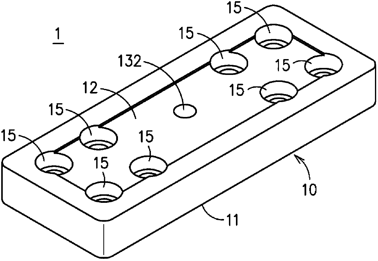
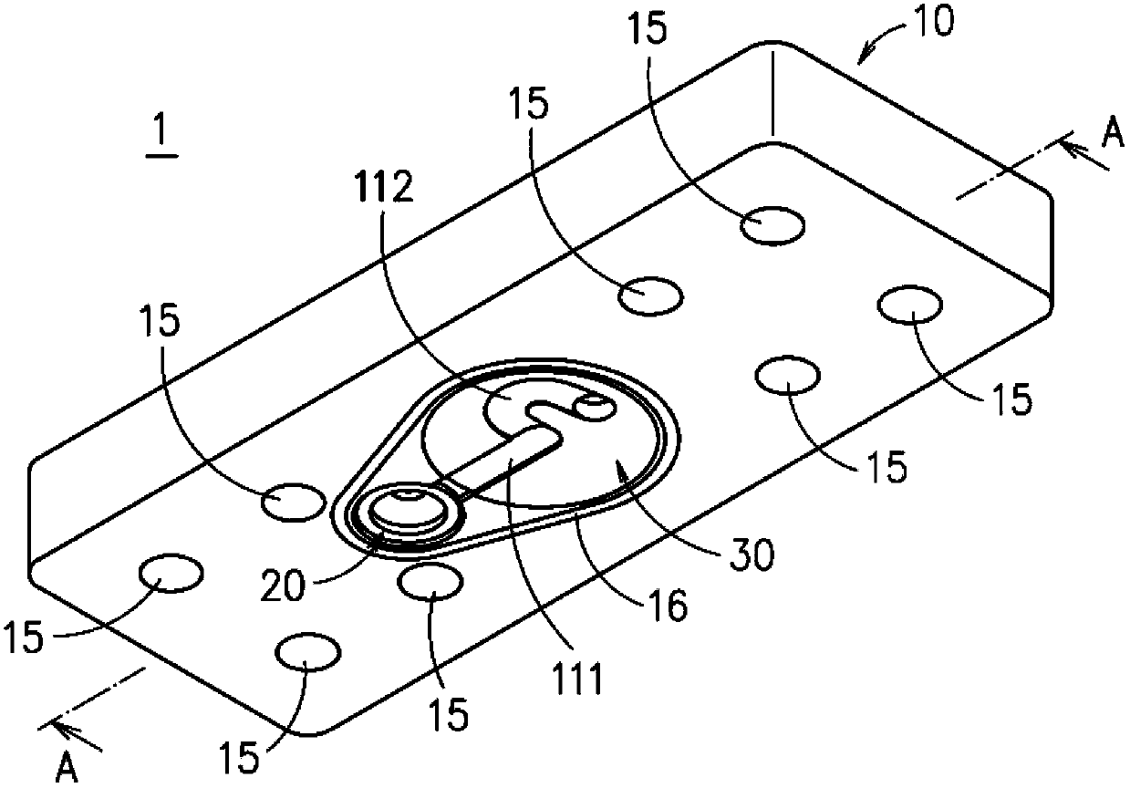
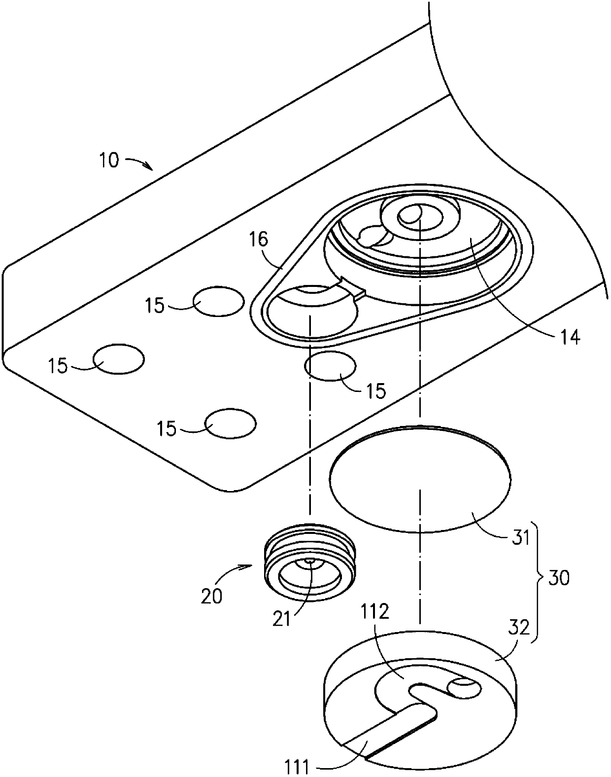
[0049] see Figure 1 to Figure 4 In the shown embodiment, the composite variable flow resistance hydrostatic slider module 1 includes a body 10, and the body 10 has an opposite mounting surface 11 (the bottom surface of the body 10 shown in the figure) and an oil chamber 12 (the body 10 shown in the figure) 10 top). A small hole restrictor 20 and a film restrictor 30 are arranged in the body 10, the small hole restrictor 20 has a first small hole 21, and the film restrictor 30 is composed of a film 31 and a circular block The block body 32 is composed of a second chamber 321 and a second small hole 322. The film 31 i...


PUM


Abstract

The present disclosure relates to a hydrostatic plate bearing, which comprises: a body, and a plurality of restrictors. Wherein, the body is formed with a mounting surface and an oil chamber that are disposed opposite to each other; the plural restrictors includes an orifice restrictor and a membrane restrictor while allowing the orifice restrictor and the membrane restrictor to be serially connected to each other. Operationally, a working fluid that is flowing into the body via the mounting surface is split to flow through the orifice restrictor and the membrane restrictor, in that the split flow of the working fluid that is flowing through the orifice restrictor is guided to flow into the oil chamber.

Description

technical field [0001] The invention relates to a hydrostatic throttling device, in particular to a composite variable flow resistance hydrostatic slider module. Background technique [0002] The types of existing fluid restrictors include film restrictors, slide-cut restrictors, capillary restrictors, orifice restrictors, and the like. Fluid restrictors are installed in various machines to buffer pressure changes between the pressure source end and the load end. An ideal restrictor should have low working pressure and high rigidity. However, looking at the existing restrictor structure, there are generally problems of high working pressure, low rigidity, high production cost, difficult adjustment and replacement, poor speed adaptability and poor stability. Damage to the flow controller and mechanical equipment. Contents of the invention [0003] The object of the present invention is to provide a composite variable flow resistance hydrostatic slider module. [0004] In...

Claims


Application Information

Patent Timeline
Patent Type & Authority Applications(China)
IPC IPC(8): F16C32/06
CPCF16L55/027
Inventor 陈尚德萧锡鸿陈柏村
Owner IND TECH RES INST
Why Eureka
Try Eureka