Camera module

A camera module, image sensor technology, applied in cameras, camera bodies, TVs, etc., can solve the problems of image quality impact, small imaging, small height, etc.

Inactive Publication Date: 2014-03-12
HONG FU JIN PRECISION IND (SHENZHEN) CO LTD +1
View PDF6 Cites 5 Cited by
  • Summary
  • Abstract
  • Description
  • Claims
  • Application Information

AI Technical Summary

Problems solved by technology

However, it is inevitable that dust will adhere to the filter during the manufacture and use of the camera module. Therefore, it is always desired that the distance between the filter and the image sensor be as large as possible. The projection on the measurement area will become smaller, and the image will be smaller. In this way, the image quality will be smaller
However, the glue is liquid before curing, and the filter needs to be pressed down during the process of adhering the filter. As a result, the height that can be maintained after the glue is cured is often small, and the distance between the filter and the image cannot be separated sensor, therefore, the imaging quality is greatly affected by dust, which is often not ideal

Method used


Image

  • Camera module
  • Camera module

Examples


Embodiment Construction

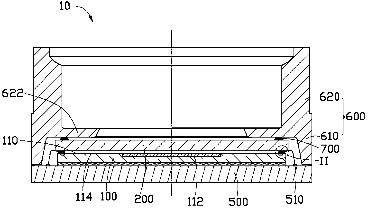
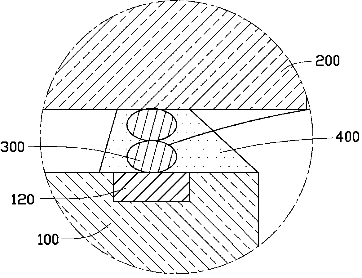
[0011] see Figure 1-2 , a camera module 10 according to a preferred embodiment of the present invention, which includes an image sensor 100 and a filter 200 . The image sensor 100 includes a light-sensing surface 110 for receiving incident light for imaging. The light-sensing surface 110 includes a sensing area 112 and a non-sensing area 114 surrounding the sensing area. The non-sensing area 114 is formed with a plurality of pads 120 . The filter 200 is disposed on the image sensor 100 . At least one metal ball 300 is stacked on at least three of the solder pads 120 . The number of the metal balls 300 on each of the bonding pads 120 is the same. The optical filter 200 is disposed on the metal ball 300 .

[0012] The camera module 10 utilizes the metal ball 300 to separate the image sensor 100 and the filter 200 at a relatively long distance, thereby reducing the influence of dust that may adhere to the filter 200 on the imaging quality and improving the imaging quality. ...


PUM

PropertyMeasurementUnit
Diameteraaaaaaaaaa

Abstract

The invention provides a camera module. The camera module comprises an image sensor and an optical filter, wherein the image sensor comprises an optical sensing surface for receiving incident light imaging, the optical sensing surface comprises a sensing area and a non-sensing area surrounding the sending area, and multiple bonding pads are formed in the non-sensing area. At least one metal ball is stacked on at least three bonding pads; the number of the metal balls of each bonding pad is the same, and the optical filter is arranged on the metal balls. According to the camera module, by use of the metal balls, the image sensor and the optical filter can be isolated at a quite long distance so that the effects exerted on imaging quality by dust possibly adhered to the optical filter can be reduced, and the imaging quality is improved.

Description

technical field [0001] The invention relates to a camera module, in particular to a camera module with a filter. Background technique [0002] A camera module generally includes an image sensor and a filter. The filter can be directly arranged on the image sensor by coating glue on the non-sensing area of ​​the image sensor, and close the sensing area of ​​the image sensor. However, it is inevitable that dust will adhere to the filter during the manufacture and use of the camera module. Therefore, it is always desired that the distance between the filter and the image sensor be as large as possible. The projection on the measurement area will become smaller, and the image will be smaller, so the image quality will be smaller. However, the glue is liquid before curing, and the filter needs to be pressed down during the process of adhering the filter. As a result, the height that can be maintained after the glue is cured is often small, and the distance between the filter an...

Claims


Application Information

Patent Timeline
IPC IPC(8): H04N5/225G03B17/12G02B7/00H01L23/00
Inventor 王宏坤
Owner HONG FU JIN PRECISION IND (SHENZHEN) CO LTD
Why Eureka
Try Eureka