Shielded wire fixing structure

A technology of shielding cables and fixing structures, which is applied in the direction of circuits, connecting parts, protective grounding/shielding devices, electrical components, etc., and can solve problems such as high manufacturing costs

Active Publication Date: 2014-03-12
YAZAKI CORP
View PDF8 Cites 2 Cited by
  • Summary
  • Abstract
  • Description
  • Claims
  • Application Information

AI Technical Summary

Problems solved by technology

[0012] However, the existing shielded connector 501 as described above has a problem of high manufacturing cost due to the use of equipment such as the core 527 and the crimping dies 523 and 525 when crimping the shielding ring 505

Method used


Image

  • Shielded wire fixing structure
  • Shielded wire fixing structure
  • Shielded wire fixing structure

Examples


Embodiment Construction

[0056] A fixing structure of a shielded cable according to an embodiment of the present invention will now be described in detail with reference to the accompanying drawings.

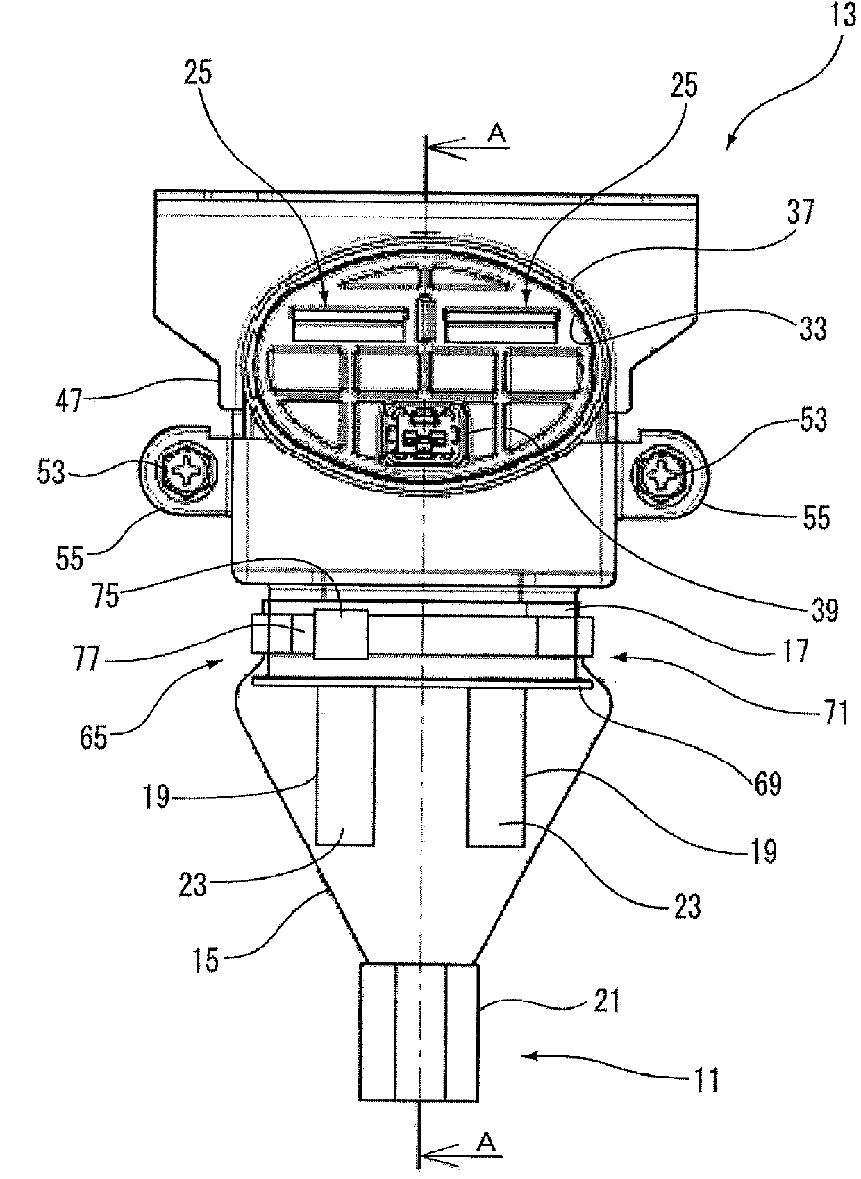
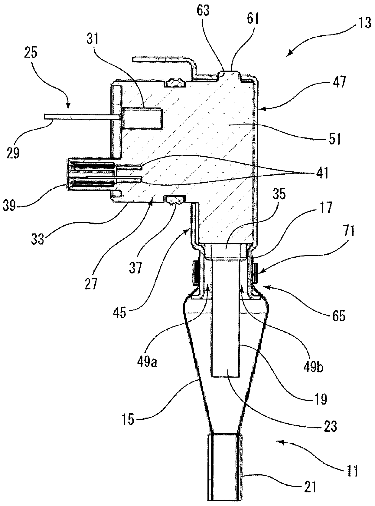
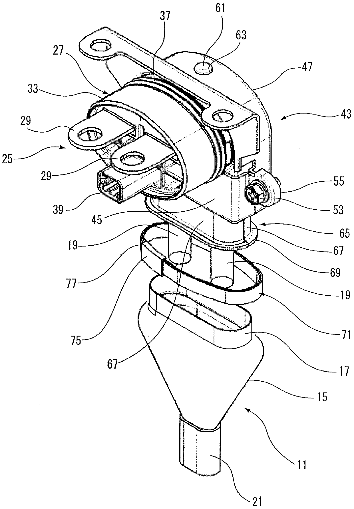
[0057] Such as Figure 1-3As shown, for example, a shielded connector 13 having a shielded cable fixing structure according to an embodiment of the present invention is installed and used in an inverter of an electric vehicle to electrically connect the inverter and a motor for on-vehicle electrical equipment.

[0058] The shielded cable 11 includes electric wires 19 , a braid 15 covering the electric wires 19 , and a sheath 21 covering the braid 15 . The electric wire 19 is composed of a core wire at its center and an insulating layer 23 formed of an insulator such as insulating resin for covering the outer periphery of the core wire. The shielded cable 11 of the present invention has a structure in which two wires are shielded together, but may have a structure in which a single wire or three or more...


PUM


Abstract

A shielded wire (11) fixing structure, provided with: a shielded wire (11) comprising a wire (19), a braid (15), and a sheath (21); an insulation housing (27) for housing a terminal piece (25) connected to the wire (19); a pair of division shield shells (43), the insulation housing (27) being fitted to the interior thereof; and a fixing band (71) that is tightened and secured in a state in which the terminal end section (17) of the braid (15) is positioned between the fixing band and an annular fitting groove (65) comprising a groove-shaped section (67) press-formed into each of the division shield shells (43) at a portion that covers the wire draw-out opening (35) of the insulation housing (27).

Description

technical field [0001] The invention relates to a shielded cable fixing structure for attaching a shielded cable to a shielding shell. Background technique [0002] As shielded connectors attached to ends of shielded cables used for power supply and wiring in various vehicles such as hybrid cars, shielded connectors such as those disclosed in Patent Document 1 and the like are known. [0003] Such as Figure 6 As shown, the shielded connector 501 has: a shield ring 505 through which the shielded cable 503 extends; and a shield shell 517 . And, the shield shell 517 includes: a hollow cylindrical small-diameter portion 513 through which the core wire and the insulating layer 511 of the shielded cable 503 from which the braid 507 and the sheath 509 have been stripped extend. The outer circumference of the diameter portion 513 is covered by the end portion of the stripped braid 507; and a hollow cylindrical main body portion 515 provided to extend from the small diameter portio...

Claims


Application Information

Patent Timeline
IPC IPC(8): H01R13/648
CPCH01R13/6581H01R13/648H01R2201/26H01R9/0524H01R13/6593H01R13/65912
Inventor 铃木徹加藤元
Owner YAZAKI CORP
Why Eureka
Try Eureka