

Sewage sedimentation tank
A settling tank and sewage technology, applied in the direction of sedimentation separation, settling tank, feeding/discharging device of settling tank, etc., can solve the problems of unsatisfactory sedimentation mode and sedimentation speed of grit chamber not reaching the expected effect, etc., to achieve Accelerate the rate of free precipitation, improve the efficiency of sewage treatment, and facilitate cleaning
- Summary
- Abstract
- Description
- Claims
- Application Information
AI Technical Summary
Problems solved by technology
Method used
Image

Examples
Embodiment 1
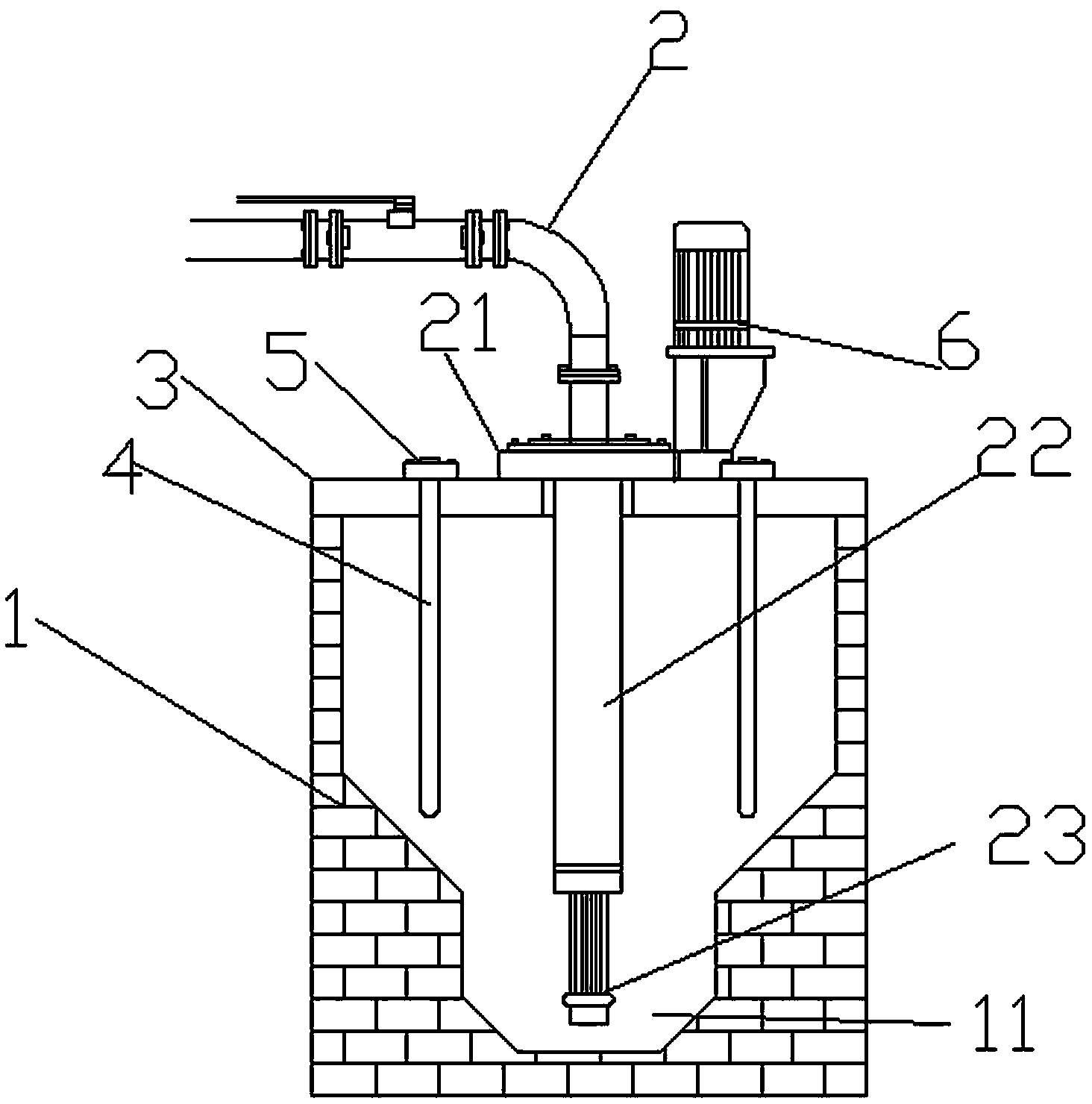
[0021] As a preferred embodiment of the present invention, the present invention includes a grit chamber 1, a drain pipe 2 and a bracket 3 arranged on the grit chamber, the sedimentation chamber 1 is funnel-shaped, and the bottom of the grit chamber 1 is provided with The bucket 11 is characterized in that: the grit chamber 1 is also provided with several vibrating rods 4, the vibrating rods 4 are arranged above the sand bucket 1, and the upper ends of the vibrating rods 4 are connected with the bracket 3, so that The bracket 3 is provided with a vibrating rod connecting block 5, the lower end of the vibrating rod connecting block 5 is connected with the vibrating rod 4 through the bracket 3, and the upper end of the vibrating rod connecting block 5 protrudes from the bracket 3 surface, the two sides of the sand bucket 11 are provided with slopes, and the bottom of the sand bucket 11 is symmetrically provided with two slopes.
[0022] In the present invention, a vibrating rod ...
Embodiment 2
[0024] As another preferred embodiment of the present invention, the present invention includes a grit chamber 1, a drain pipe 2 and a bracket 3 arranged on the grit chamber, the sedimentation chamber 1 is funnel-shaped, and the bottom of the grit chamber 1 is provided with The sand bucket 11 is characterized in that: the grit chamber 1 is also provided with several vibrating rods 4, the vibrating rods 4 are arranged above the sand bucket 1, and the upper ends of the vibrating rods 4 are connected with the bracket 3, The bracket 3 is provided with a vibrating rod connecting block 5, the lower end of the vibrating rod connecting block 5 is connected with the vibrating rod 4 through the bracket 3, and the upper end of the vibrating rod connecting block 5 protrudes from the bracket. On the surface of the frame 3, slopes are arranged on both sides of the sand bucket 11, and two slopes are symmetrically arranged on the bottom of the sand bucket 11.
[0025] In the present invention...
Embodiment 3
[0029] As another preferred embodiment of the present invention, the present invention includes a grit chamber 1, a drain pipe 2 and a bracket 3 arranged on the grit chamber, the sedimentation chamber 1 is funnel-shaped, and the bottom of the grit chamber 1 is provided with The sand bucket 11 is characterized in that: the grit chamber 1 is also provided with several vibrating rods 4, the vibrating rods 4 are arranged above the sand bucket 1, and the upper ends of the vibrating rods 4 are connected with the bracket 3, The bracket 3 is provided with a vibrating rod connecting block 5, the lower end of the vibrating rod connecting block 5 is connected with the vibrating rod 4 through the bracket 3, and the upper end of the vibrating rod connecting block 5 protrudes from the bracket. On the surface of the frame 3, slopes are arranged on both sides of the sand bucket 11, and two slopes are symmetrically arranged on the bottom of the sand bucket 11.
[0030] In the present invention...
PUM
 Abstract
Description
Claims
Application Information