Suction cup device and crane

A suction cup and motor technology, which is applied in the field of machinery, can solve the problems of large labor consumption and low efficiency of operators, and achieve the effects of saving manpower, improving safety and improving efficiency.

Active Publication Date: 2014-03-19
SOUTHWEST ALUMINUM GRP
View PDF5 Cites 2 Cited by
  • Summary
  • Abstract
  • Description
  • Claims
  • Application Information

AI Technical Summary

Problems solved by technology

[0003] However, the inventor found in the research process of the present application that when the cranes of the prior art are used to lift objects, when the materials to be lifted are heavy, the operator needs to spend a lot of power, and the efficiency is low.

Method used


Image

  • Suction cup device and crane
  • Suction cup device and crane
  • Suction cup device and crane

Examples


Embodiment Construction

[0040] The following will clearly and completely describe the technical solutions in the embodiments of the present invention with reference to the accompanying drawings in the embodiments of the present invention. Obviously, the described embodiments are only some, not all, embodiments of the present invention. Based on the embodiments of the present invention, all other embodiments obtained by persons of ordinary skill in the art without creative efforts fall within the protection scope of the present invention.

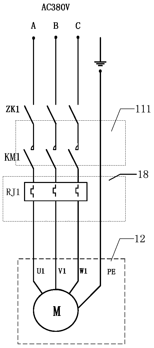
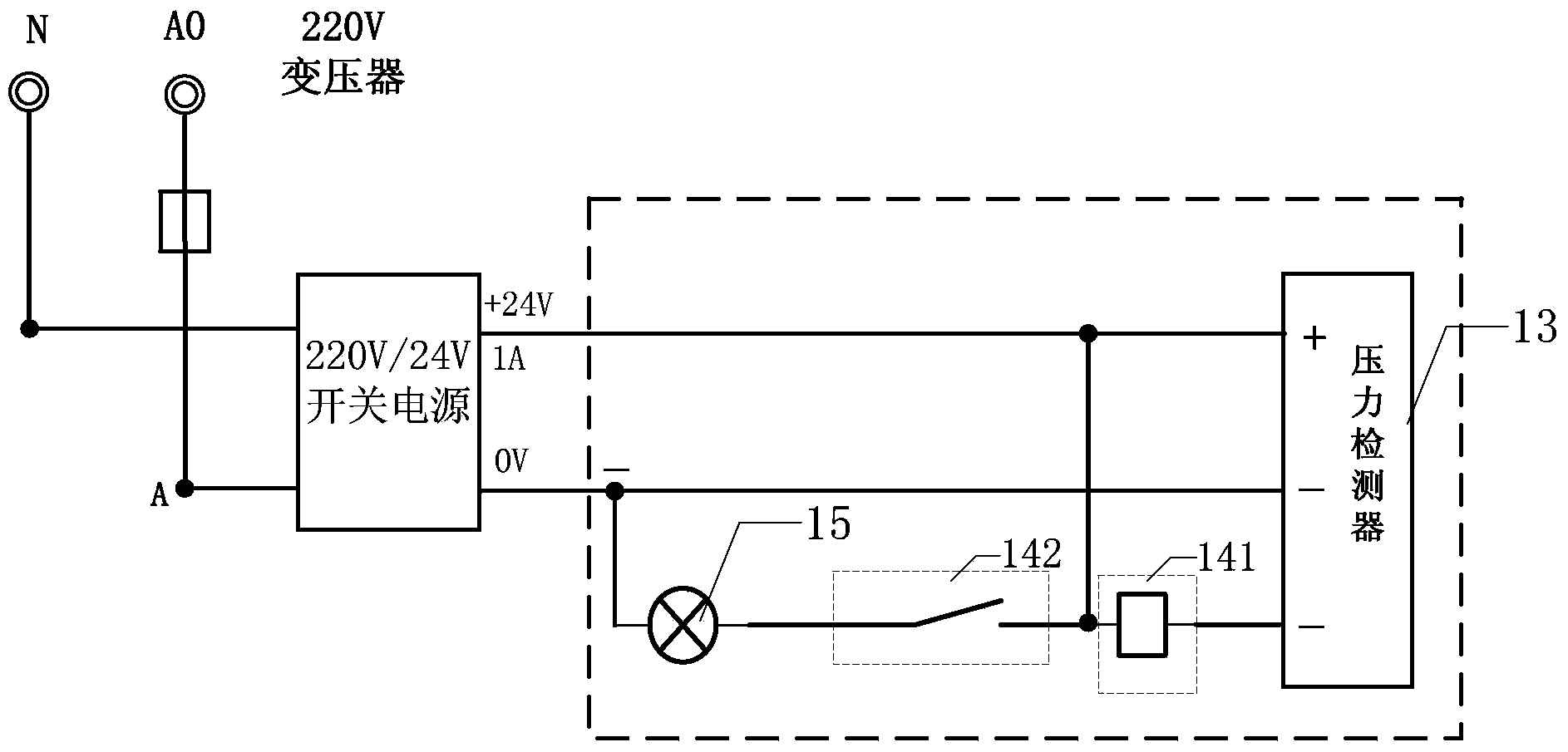
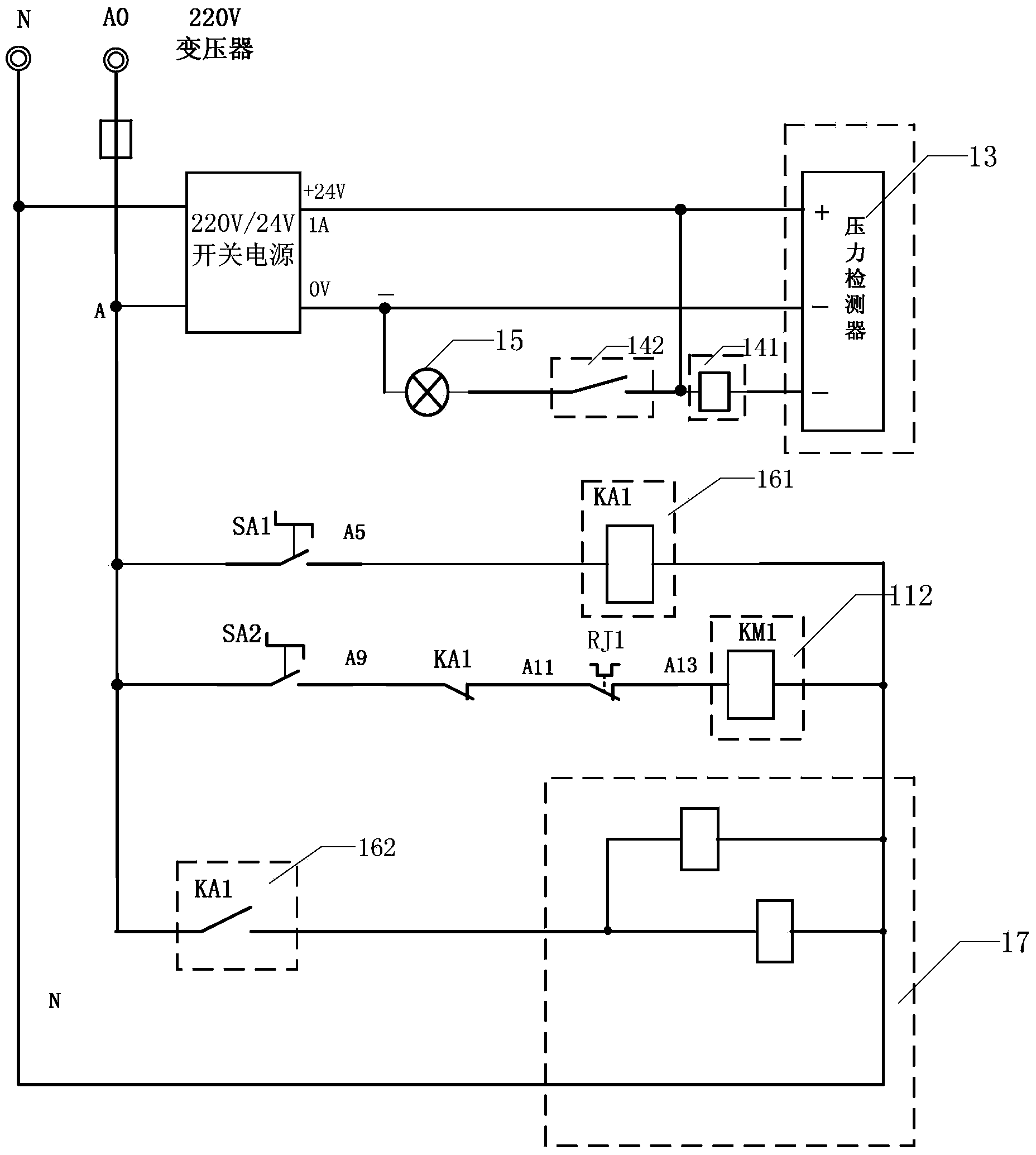
[0041] In order to solve the problem of low efficiency when lifting materials in the prior art, the present application discloses a sucker device. The sucker device includes: a contactor, a motor 12 , a wire reel, a sucker hanger, a vacuum pump, a pressure detector 13 , a first relay and a pressure alarm 15 .

[0042] see figure 1 The schematic diagram of the connection relationship between the motor and the contactor is shown, wherein the contact 111 of the conta...


PUM


Abstract

The invention discloses a suction cup device and a crane. The suction cup device comprises a contactor, an electric motor, a winder, a suction cup hanger, a vacuum pump, a pressure detector, a first relay and a pressure alarm, when a material needs to be hoisted, the contactor and the corresponding power supply are communicated by an operator, so that the contactor is communicated with the electric motor to start the electric motor; the electric motor is started to control the vacuum pump to suck air from inside of the suction cup hanger to enable a suction cup to be vacuumized and form pressure; and the pressure detector detects pressure in an air flowing loop of the suction cup hanger, when the pressure value reaches the setting value, the pressure detector is communicated with the first relay and the pressure alarm, and the pressure alarm performs alarming operation to indicate the suction cup hanger to be in a working state, and then the operator can control a crane carriage to hoist the material, the operation is labor-saving and the efficiency is improved.

Description

technical field [0001] The invention relates to the mechanical field, in particular to a suction cup device and a crane. Background technique [0002] Cranes, also known as overhead cranes, are widely used in indoor and outdoor warehouses, workshops, docks, and open-air storage yards. They are usually equipped with lifting trolleys, and the lifting trolleys are composed of a lifting mechanism, a trolley operating mechanism and a trolley. The frame consists of three parts. Wherein, the lifting mechanism includes a motor, a brake, a reducer, a reel and a pulley block, and the operator operates the motor to drive the reel to rotate through the reducer to realize the lifting of the material. [0003] However, the inventor found in the research process of the present application that when using the crane of the prior art to lift items, when the material to be lifted is heavy, the operator needs to spend a lot of power and the efficiency is low. Contents of the invention [00...

Claims


Application Information

Patent Timeline
Patent Type & Authority Applications(China)
IPC IPC(8): B66C1/02
Inventor 杨道杰周灵游志强陈玉东
Owner SOUTHWEST ALUMINUM GRP
Why Eureka
Try Eureka