
Steel wire creep property testing machine

A testing machine and creep test technology, applied in the direction of testing the ductility of materials, etc., can solve the problems of unstable experimental force, difficult control of material temperature, constant temperature of steel wire, stable test environment, errors, etc.

Inactive Publication Date: 2014-03-19
ADVANCED MFG TECH CENT CHINA ACAD OF MASCH SCI & TECH
View PDF4 Cites 5 Cited by
  • Summary
  • Abstract
  • Description
  • Claims
  • Application Information

AI Technical Summary

Problems solved by technology

Most of the existing tensile or compressive creep test devices for materials use simple lever-type or hydraulic jack-type loading racks. The experimental devices are convenient and flexible to use, but it is difficult to achieve continuous loading of arbitrary loads, the test force is unstable, and the distance cannot be adjusted. Adjustment, data collection is manually recorded with a scale, which is very easy to cause errors and other shortcomings. In addition, the commonly used material mechanics testing machine can be used for creep experiments of steel wires. Its performance in terms of experimental force loading and data is superior, but in the material In terms of temperature control, it is difficult to achieve a constant steel wire temperature and a stable test environment

Method used


Image

  • Steel wire creep property testing machine
  • Steel wire creep property testing machine

Examples


Embodiment Construction

[0014] The embodiments of the present invention will be described in detail below with reference to the accompanying drawings, but the present invention can be implemented in many different ways defined and covered by the claims.

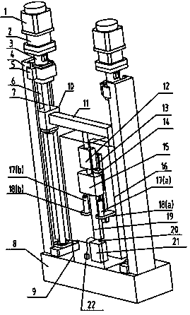
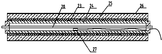
[0015] Steel wire creep performance test process: First, according to the steel wire to be tested, the steel wire 20 is first installed on the lower wire fixer; the copper tube is selected as the heating tube 24, and the electric heating belt 23 is wound on the copper tube to ensure that the electric heating belt is in the The upper part and the lower part of the heating tube are tight, and the middle part is sparse; then the outer layer of the heating belt is wrapped around the thermal insulation cotton 25; the thermal insulation cotton is wrapped tightly with the winding belt 26; The middle part; the electric heating band, the temperature sensor are connected with the temperature controller 22, and the two ports of the heating pipe are sealed with ...


PUM


Abstract

The invention provides a steel wire creep property testing machine. The testing machine mainly comprises a testing machine base, a wire fixing device, a tension sensor, a loading beam, displacement measuring sensors, a heating device and a thermostat, wherein the wire fixing device comprises an upper steel wire fixer and a lower steel wire fixer, and the upper steel wire fixer can move up and down along a guide device, so that the testing machine is suitable for testing steel wires with different length; the tension sensor is arranged above the upper wire fixer and used for detecting the magnitude of load and feeding the magnitude to a control terminal, and the stress on a steel wire is controlled to be constant by virtue of a loading system; the loading beam on a movable screw seat can be driven to move by a servo motor and exert a certain load to the steel wire; the measuring head of each displacement measuring sensor can move up and down along with the upper steel wire fixer, so that the creep of the steel wire can be tested in real time; the heating device is used for heating the steel wire and keeping constant test temperature; the thermostat can be used for maintaining a stable temperature environment during the test. The testing machine can achieve continuous loading of any load and keep a constant test stress, and the temperature of the steel wire can be adjusted intelligently; the load, the temperature and the displacement of the steel wire can be collected easily, so that the testing machine is beneficial to test research on creep of steel wires.

Description

technical field [0001] The invention relates to the field of material testing, in particular to a steel wire creep performance testing machine. Background technique [0002] To test the creep performance of steel wire, the main test is to test the relationship between the deformation of the material and the time change under the action of a certain ambient temperature and a constant external force. Most of the existing tensile or compressive creep test devices for materials use simple lever-type or hydraulic jack-type loading racks. The experimental devices are convenient and flexible to use, but it is difficult to achieve continuous loading of arbitrary loads, the test force is unstable, and the distance cannot be adjusted. Adjustment, data collection is manually recorded with a scale table, which is very easy to cause errors and other shortcomings. In addition, the commonly used material mechanics testing machine can be used for creep experiments of steel wires. Its perfor...

Claims


Application Information

Patent Timeline
IPC IPC(8): G01N3/28
Inventor 单忠德陈海波李乃亮刘丰王素洁聂军刚
Owner ADVANCED MFG TECH CENT CHINA ACAD OF MASCH SCI & TECH
Learn More