LED lamp pin polarity detection apparatus

A technology of LED lamp and polarity detection, which is applied in the direction of measuring devices, measuring electricity, and measuring electric variables, etc., can solve the problem of inconvenient polarity detection of SMD LED lamp pins, and achieve the goal of not being easily lost, saving resources, and increasing usage the effect of time

Active Publication Date: 2014-03-19
佛山市顺德区科测技术服务有限公司
View PDF4 Cites 7 Cited by
  • Summary
  • Abstract
  • Description
  • Claims
  • Application Information

AI Technical Summary

Problems solved by technology

[0008] The technical problem to be solved by the present invention is to provide a polarity detection device for LED lamp pins, which solves the problem of inconvenient polarity detection of patch LED lamp pins in the prior art

Method used


Image

  • LED lamp pin polarity detection apparatus

Examples


Embodiment Construction

[0024] The technical scheme of the present invention is described in detail below in conjunction with accompanying drawing and embodiment:

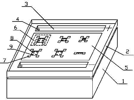
[0025] Such as figure 1 As shown, a polarity detection device for LED lamp pins includes a lower box body 1 and an upper box body 2, and the upper box body 2 is arranged on the upper part of the lower box body 1; the upper box body 2 and the lower box body 1 A through hole is provided between them, a power supply is provided in the lower box body 1, and the positive and negative lead wires of the power supply are output to the upper box body 2 through the through hole, and an LED lamp assembly 6 is arranged in the upper box body 2; the LED lamp assembly 6 includes The LED light pin contact pad 9 corresponding to the LED light pin; through the positive and negative output leads of the power supply respectively contacting two different LED light pin contact pads 9, the polarity of the LED light pin and its corresponding LED light pin are ju...


PUM


Abstract

The invention discloses an LED lamp pin polarity detection apparatus. The apparatus comprises au upper box body and a lower box body, wherein the upper box body is arranged at the upper portion of the lower box body, a through hole is arranged between the upper box body and the lower box body, the lower box body is internally provided with a power source, the positive lead wire and the negative lead wire of the power source are outputted to the upper box body through the through hole, the upper box is internally provided with an LED lamp assembly, the LED lamp assembly comprises LED lamp pin contact welding pads corresponding to LED lamp pins, and the two different LED lamp pin contact welding pads are respectively contacted through the positive output lead wire and the negative output lead wire of the power source so as to determine polarities of the LED lamp pins and a corresponding LED lamp color. According to the invention, the power source is arranged in the lower box body, and the LED lamp assembly is arranged in the upper box body so that the detection of the polarities of the LED lamp pins is facilitated, the apparatus is not easily lost during a use process, and the apparatus can be reused.

Description

technical field [0001] The invention discloses a polarity detection device for LED lamp pins, which is used for detecting LED lamp pins in the production and research process of LED factories, and belongs to the field of LED production. Background technique [0002] During the production process, or during the R&D and sample process, or during the maintenance process, the LED factory often needs to confirm the polarity of the SMD LED lamp pins. The current practice is to manually solder the positive and negative electrodes of the battery to two wires. At the same time, place the SMD LED lamp on the table, use two wires to touch different LED lamp pins respectively, and observe the polarity and the color of the LED lamp pins. [0003] This method is the most primitive and stupid way, and there are still many shortcomings, such as: [0004] (1) The battery wiring of manual welding is not firm during use and is easy to break. [0005] (2) This kind of simple equipment is easy...

Claims


Application Information

Patent Timeline
Patent Type & Authority Applications(China)
IPC IPC(8): G01R31/06
Inventor 周桃英王香兵唐豪
Owner 佛山市顺德区科测技术服务有限公司
Why Eureka
Try Eureka