Broadband dual-polarized antenna

A dual-polarized antenna and dual-polarization technology, applied in the field of communications, can solve the problems of narrowing the downtilt angle range of the antenna, low-frequency cross-area interference, limited improvement, etc., to improve impedance and isolation indicators, improve cross-polarity The effect of the conversion ratio index and the improvement of the isolation index

Active Publication Date: 2014-03-19
GCI SCI & TECH
5 Cites 13 Cited by

AI-Extracted Technical Summary

Problems solved by technology

At this stage, the VSWR and isolation indicators are mainly improved by optimizing the form and size of the radiation oscillator itself, but the degree of improvement in this way is limited, and it is difficult to meet the wide-band multi-standard applications.
The cross-polarization ratio and the front-to-back ratio are two important indicators in the horizontal plane radiation characteristics. For ultra-wideband antennas, the high-frequency cross-polarization ratio and the low-frequency front-to-back ratio are two key factors that restrict the horizontal plane radiation performance....

Method used

In the first embodiment of this broadband dual-polarized antenna, as shown in Figures 1 and 2, each radiation unit includes two parasitic radiation slots, which are longitudinally symmetrically distributed on both sides of the dual-polarized vibrator main body 5 , the vertical center distance between each slit and the dual-polarized vibrator main body 5 is 0.1-0.3 central working wavelength. By optimizing the size and specific position of the parasitic radiation slot, the front-to-back ratio of the entire radiation unit can be increased by 2dB-6dB, and the isolation index of the radiation unit can be improved to a certain extent. The longitudinal direction is the direction along the length of the reflecting plate, ...

Abstract

The invention discloses a broadband dual-polarized antenna. 2 or 4 spurious radiation slots are disposed around each dual-polarized oscillator body on a reflecting plate, the front-to-rear ratio of an antenna array may be improved by 2dB to 6dB, and an isolation index is improved to some extent. In addition, by the use of isolation components, not only the convergence of an S parameter of a radiation unit and the impedance and isolation index of the antenna array are significantly improved, but also cross polarization ratio indicators of a horizontal plane of a directional diagram of the antenna array are substantially improved. The broadband dual-polarized antenna meets the demand for high performance in terms of wide frequency bands of current base station antennas, and has good application prospects in the field of communication.

Application Domain

Radiating elements structural formsPolarised antenna unit combinations +1

Technology Topic

Image

  • Broadband dual-polarized antenna
  • Broadband dual-polarized antenna
  • Broadband dual-polarized antenna

Examples

  • Experimental program(1)

Example Embodiment

[0016] In order to make the objectives, technical solutions, and advantages of the present invention clearer, the following further describes the present invention in detail with reference to the accompanying drawings and embodiments. It should be understood that the specific embodiments described herein are only used to explain the present invention, and do not limit the protection scope of the present invention.
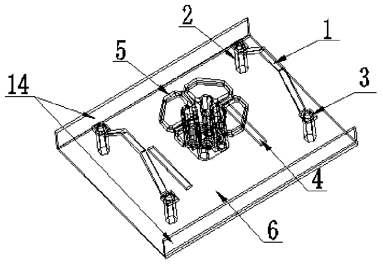
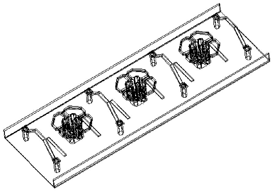
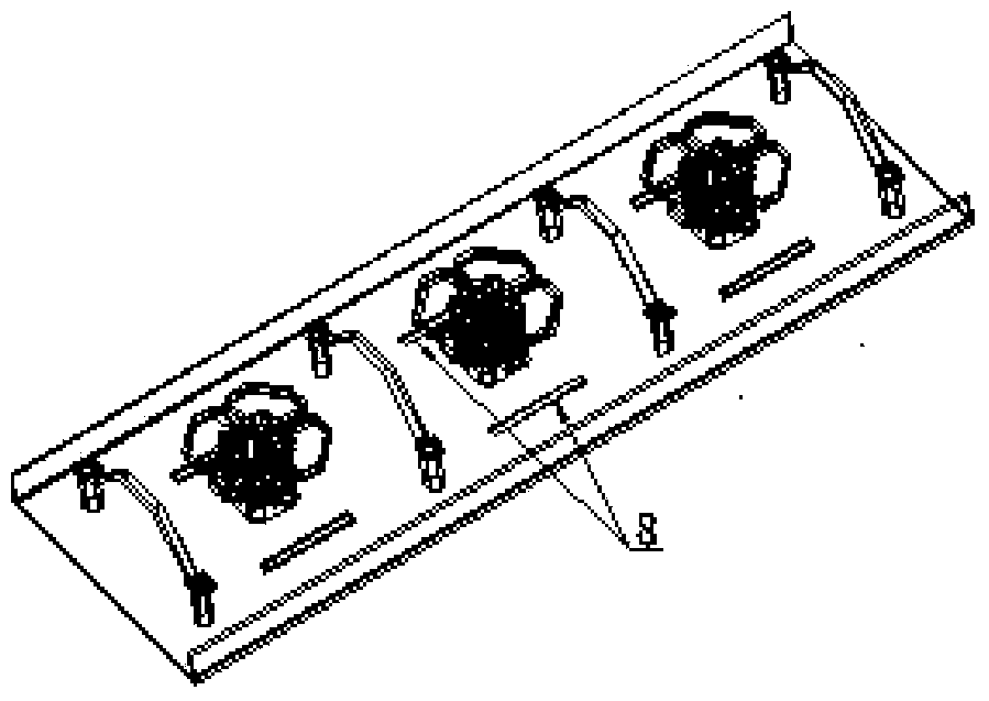
[0017] The wide-band dual-polarized antenna of the present invention is a wide-band dual-polarized antenna with high-radiation performance, which includes at least one dual-polarized vibrator body, at least two isolation components, and a reflector.
[0018] The dual-polarized vibrator main body includes a vibrator radiating arm and a supporting balun, and each dual-polarized vibrator main body is sequentially installed on the reflector to form an array, two ends of the array, and two adjacent dipoles One of the isolation components is respectively installed between the main bodies of the oscillating element, and the reflector is provided with two or four rectangular grooves near the position of the main body of each dual-polarization oscillating element, and each rectangular groove becomes a parasitic radiation gap.
[0019] Such as figure 1 As shown, a dual-polarized vibrator body 5, its surrounding parasitic radiation gap 4 and the isolation group (isolation components composed of 1, 2, 3) form a radiating unit, and the transverse section of the radiating unit is as Figure 7 Shown.
[0020] The main body of the dual polarization oscillator can be figure 1 The form shown in mark 5 can also be Image 6 The form shown in the mark 7 or other types of equivalent symmetrical vibrator forms are manufactured by sheet metal or die-casting processes. The main body of the vibrator is located at the transverse center of the reflector 6, and the height is approximately 1/4 of the central working wavelength. , As the main radiation part to transmit and receive electromagnetic signals. The central operating wavelength is the central operating wavelength of the broadband dual-polarized antenna.
[0021] The parasitic radiation gap is a rectangular slot opened on the reflector, such as figure 1 In the form shown in the label 4, the slot length is 0.2 to 0.5 central working wavelength, and the width is 0.01 to 0.04 central working wavelength.
[0022] In the first embodiment of this broadband dual-polarized antenna, such as figure 1 , 2 As shown, each radiating unit includes two parasitic radiation slots, which are longitudinally symmetrically distributed on both sides of the dual-polarization vibrator body 5. The distance between each slot and the vertical center of the dual-polarization vibrator body 5 is 0.1 to 0.3 central working wavelengths. . By optimizing the size and specific location of the parasitic radiation slot, the front-to-back ratio of the entire radiating unit can be increased by 2dB to 6dB, and the isolation index of the radiating unit can be improved to a certain extent. The longitudinal direction is the direction along the length of the reflector, or along the direction in which the radiation units are arranged, and the following directions are all based on this.
[0023] In the second embodiment of the broadband dual-polarized antenna, the parasitic radiation slots can also be laterally symmetrically distributed on both sides of the main body of the dual-polarized dipole. The specific implementation form is as follows: image 3 As shown in the mark 8, its size and specific position are consistent with the first embodiment.
[0024] In the third embodiment of the broadband dual-polarized antenna, each radiating unit can also include 4 parasitic radiation slots, and each pair is symmetrically distributed longitudinally and laterally on both sides of the dual-polarized dipole body. The specific implementation form Such as Figure 4 As indicated by the mark 9 in the middle, its size and specific position are consistent with the first embodiment.
[0025] In the fourth embodiment of the broadband dual-polarized antenna, each radiating element may also include 4 parasitic radiation slots, each pair is symmetrically distributed in the +45° and -45° directions on the main body of the dual-polarized dipole. On both sides, the specific implementation form is as Figure 5 As shown in the mark 10, its size and specific position are consistent with the first embodiment.
[0026] Image 6 In the broadband dual-polarized antenna shown, the main body of the dual-polarized dipole is different from those in the other embodiments, and can be used as the fifth embodiment.
[0027] The two isolation components are symmetrically distributed on both sides of the dual-polarized vibrator body. Preferably, the vertical center distance between each isolation component and the vibrator body is 0.35 to 0.45 central operating wavelengths, as specifically figure 1 Shown. In the antenna array, the vertical center distance between each isolation component and the adjacent dipole main body is 1/2 of the distance between the adjacent dipole main bodies, such as figure 2 Shown.
[0028] As a preferred embodiment, the transverse section of the isolating component is as Figure 7 As shown in the figure, each isolation component is composed of a "several" shaped metal sheet (preferably aluminum sheet), two plastic studs 2 and four plastic screws 3; wherein the aluminum sheet includes an upper section 1, Two inclined sections 12 and two lower sections 13, in which the length of the upper section 1 is 0.1~0.25 central working wavelength, the width is 3mm~10mm, they are placed parallel to the reflector, and the distance from the vertical center of the reflector is 0.25~0.5 Center working wavelength. The angle A between the inclined section 12 and the upper section 1 is between 10° and 50°, and the width is the same as that of the upper section 1. The length and width of the lower section 13 range from 5 mm to 15 mm, and it is tightly connected to the plastic stud 2 by a plastic screw 3. The entire aluminum sheet is processed by sheet metal, and the thickness ranges from 1 to 3 mm. The height of the plastic stud 2 ranges from 10 mm to 30 mm, and the distance between the two plastic studs is 0.45 to 0.7 center operating wavelengths. The plastic stud and the launching board are connected together by plastic screws.
[0029] The use of isolation components not only significantly improves the convergence of the S parameters of the radiating element, improves the impedance and isolation indexes of the radiating element and its antenna array, but also greatly improves the cross-polarization of the radiating element and its array pattern horizontal plane Ratio index. The insulating contact between the isolation component and the reflector also ensures the intermodulation index. In addition, because the bent aluminum sheet adopts a "several"-shaped structure, structural deformation can be effectively avoided.
[0030] The radiation unit is located on the reflector 6, and the directional pattern can be optimized by adjusting the width of the reflector and the size of the side edge 14. The array of radiating elements such as Figure 2-6 As shown, by reasonably optimizing the size, a base station antenna array that meets usage requirements can be obtained.
[0031] The relative bandwidth of the above-mentioned radiating element and the antenna array formed by it is above 40%, the axial cross-polarization ratio index in the horizontal plane pattern is greater than 25dB, the ±60° cross-polarization ratio is greater than 15dB, and the front-to-rear ratio is greater than 27dB, which can fully meet the current requirements. Broadband and high performance requirements for base station antennas. Compared with the existing base station radiating unit and antenna array, it not only has better impedance and isolation indexes, but also significantly improves the cross-polarization ratio and front-to-back ratio indexes of the radiation horizontal plane, while ensuring structural stability and intermodulation indexes. .
[0032] The above-mentioned embodiments only express several implementation modes of the present invention, and their description is more specific and detailed, but they should not be interpreted as a limitation on the patent scope of the present invention. It should be pointed out that for those of ordinary skill in the art, without departing from the concept of the present invention, several modifications and improvements can be made, and these all fall within the protection scope of the present invention. Therefore, the protection scope of the patent of the present invention should be subject to the appended claims.

PUM

PropertyMeasurementUnit
Thickness1.0 ~ 3.0mm
tensileMPa
Particle sizePa
strength10

Description & Claims & Application Information

We can also present the details of the Description, Claims and Application information to help users get a comprehensive understanding of the technical details of the patent, such as background art, summary of invention, brief description of drawings, description of embodiments, and other original content. On the other hand, users can also determine the specific scope of protection of the technology through the list of claims; as well as understand the changes in the life cycle of the technology with the presentation of the patent timeline. Login to view more.

Similar technology patents

Function optimization method, device and system

PendingCN111027666AImprove optimization efficiencyImprove convergenceArtificial lifeFunction optimizationChemotaxis
Owner:STATE GRID JIBEI ELECTRIC POWER COMPANY LIMITED CHENGDE POWER SUPPLY +1

Processing method for burnup constraints in spacecraft flight game

ActiveCN113221365AImprove convergenceImprove efficiencyDesign optimisation/simulationConstraint-based CADSpacecraftReal-time computing
Owner:BEIJING INSTITUTE OF TECHNOLOGYGY

Classification and recommendation of technical efficacy words

Why Eureka
Try Eureka