Link transmission method of optical fiber repeater

A technology of optical fiber repeater and transmission method, which is applied in the field of wireless communication relay transmission, and can solve problems such as the failure of optical fiber repeater to meet the requirements of relay communication, installation of relay equipment, and mutual interference of signals

Active Publication Date: 2018-11-09
嘉兴力托机械股份有限公司
View PDF3 Cites 0 Cited by
  • Summary
  • Abstract
  • Description
  • Claims
  • Application Information

AI Technical Summary

Problems solved by technology

[0002] In the current wireless system, there are many kinds of wireless communication systems, such as GSM, WCDMA, TD-SCDAM, CDMA2000, intercom private network and other wireless communication systems. In the existing technology, the above wireless communication systems have their own The dedicated optical fiber repeater is used as a relay device, but in some special areas and tunnels, due to the inconsistency of the network planning of each wireless communication system, the location of the base station of each system, the limitation of the number of optical fibers, the number of links of the optical fiber repeater, and the optical transmission route Influenced by factors such as inconsistent length and user distribution, mutual interference, and isolation requirements between systems, in these areas, all relay equipment cannot be installed in them to meet the relay requirements of various wireless communication systems. Therefore, the existing The optical fiber repeater cannot meet the relay communication requirements of each wireless communication system user in this type of area; the comparative technology similar to the present invention is: Patent No. 2010100280127, linking optical fiber repeater signal transmission method and linking optical fiber direct put station, which introduces some technical solutions to solve the above problems, but in practical applications, this technology uses analog signals to transmit in the optical transmission system, which makes the signals between channels prone to mutual interference, and in the optical transmission system The transmission distance is relatively short, and the purpose of the invention cannot be effectively realized

Method used


Image

  • Link transmission method of optical fiber repeater
  • Link transmission method of optical fiber repeater
  • Link transmission method of optical fiber repeater

Examples


Embodiment Construction

[0019] Below take accompanying drawing as an example to illustrate the embodiment of the present invention:

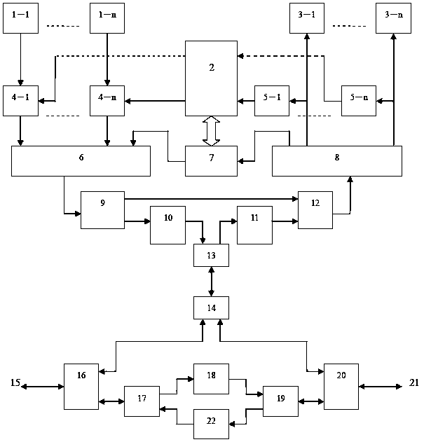
[0020] figure 1It is an electrical principle diagram of a link-type optical fiber repeater station according to an embodiment of the present invention. Composed of an optical splitter, an optical transmission transmitter, and an optical transmission receiver, it is characterized in that there are multiple signal characteristic parameter detectors, multiple programmable signal amplitude-frequency and delay characteristic parameter regulators, and an analog-to-digital converter A time-division multiplexer, a wireless receive signal power divider, a wireless transmit signal combiner, a time-division multiplexer including a digital-to-analog converter, a subcarrier transmission modem, and a transmission direction optical splitter , two external optical splitters, two optical signal amplification and transmission splitters, two optical signal amplifiers, figure 1 Middle:...


PUM


Abstract

The invention provides a chain type transmission method for a fiber optic repeater. A link type fiber optic repeater comprises a power supply, a microprocessor, an antenna system, a wireless receiver, a wireless transmitter, an outside optical fiber, a combiner, a power splitter, a time-division multiplexer comprising an analog-digital converter, a time-division multiplexer comprising a digital-to-analog converter, an optical splitter, an optical transmission transmitter and an optical transmission receive. The wireless communication relay transmission service can be provided for various wireless communication system users in special areas and tunnels, the numbers of used optical fibers is reduced, the interference between systems is reduced, the optical relay transmission and isolation between systems can be improved, and the link type fiber optic repeater has the characteristic of conducting relay transmission on various wireless communication systems.

Description

technical field [0001] The invention is a wireless communication relay transmission technology, which is suitable for relay transmission of a wireless communication system in a weak field section, and belongs to the technical field of wireless communication. Background technique [0002] In the current wireless system, there are many kinds of wireless communication systems, such as GSM, WCDMA, TD-SCDAM, CDMA2000, intercom private network and other wireless communication systems. In the existing technology, the above wireless communication systems have their own The dedicated optical fiber repeater is used as a relay device, but in some special areas and tunnels, due to the inconsistency of the network planning of each wireless communication system, the location of the base station of each system, the limitation of the number of optical fibers, the number of links of the optical fiber repeater, and the optical transmission route Influenced by factors such as inconsistent leng...

Claims


Application Information

Patent Timeline
Patent Type & Authority Patents(China)
IPC IPC(8): H04B10/291
CPCH04B10/291
Inventor 耿直
Owner 嘉兴力托机械股份有限公司
Why Eureka
Try Eureka