
Vertebral fixation device

A technology of fixing device and spine, applied in the field of spine fixing device

Inactive Publication Date: 2014-03-19
IMPLANET SA
View PDF2 Cites 3 Cited by
  • Summary
  • Abstract
  • Description
  • Claims
  • Application Information

AI Technical Summary

Problems solved by technology

However, the system still has drawbacks here

Method used


Image

  • Vertebral fixation device
  • Vertebral fixation device
  • Vertebral fixation device

Examples


Embodiment Construction

[0047] In the following description, the same numerals will be used to denote the same elements.

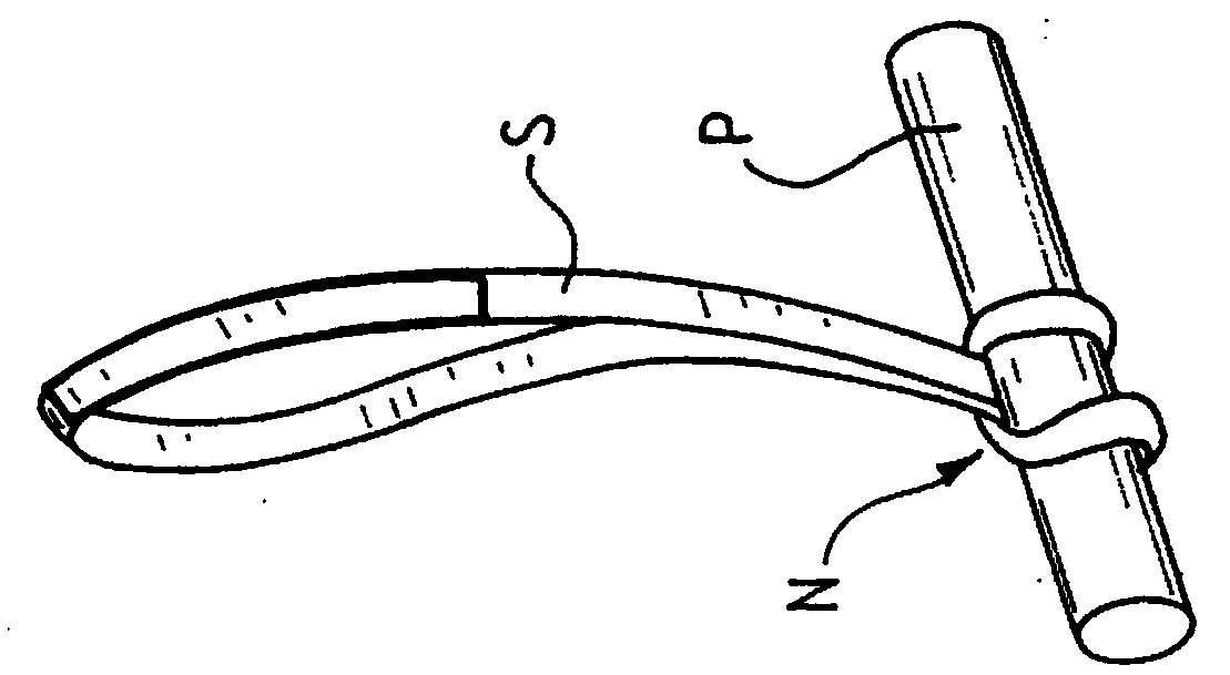
[0048] figure 1 Given the principle of the double hitch N, as implemented with a strap or strap S around the tubular member P, this allows a secure and locking fixation of one over the other.

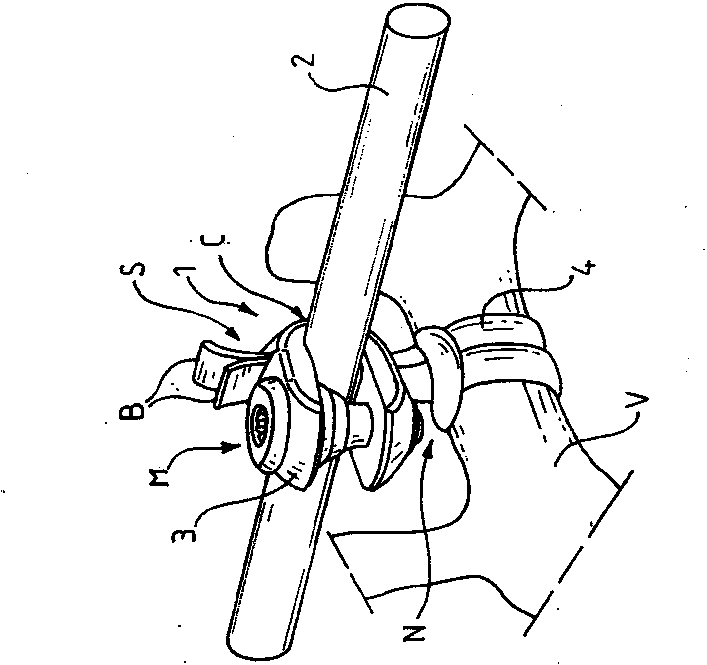
[0049] figure 2 A spinal fixation device 1 for holding a vertebra V (partially shown) on a cylindrical rod 2 is shown.

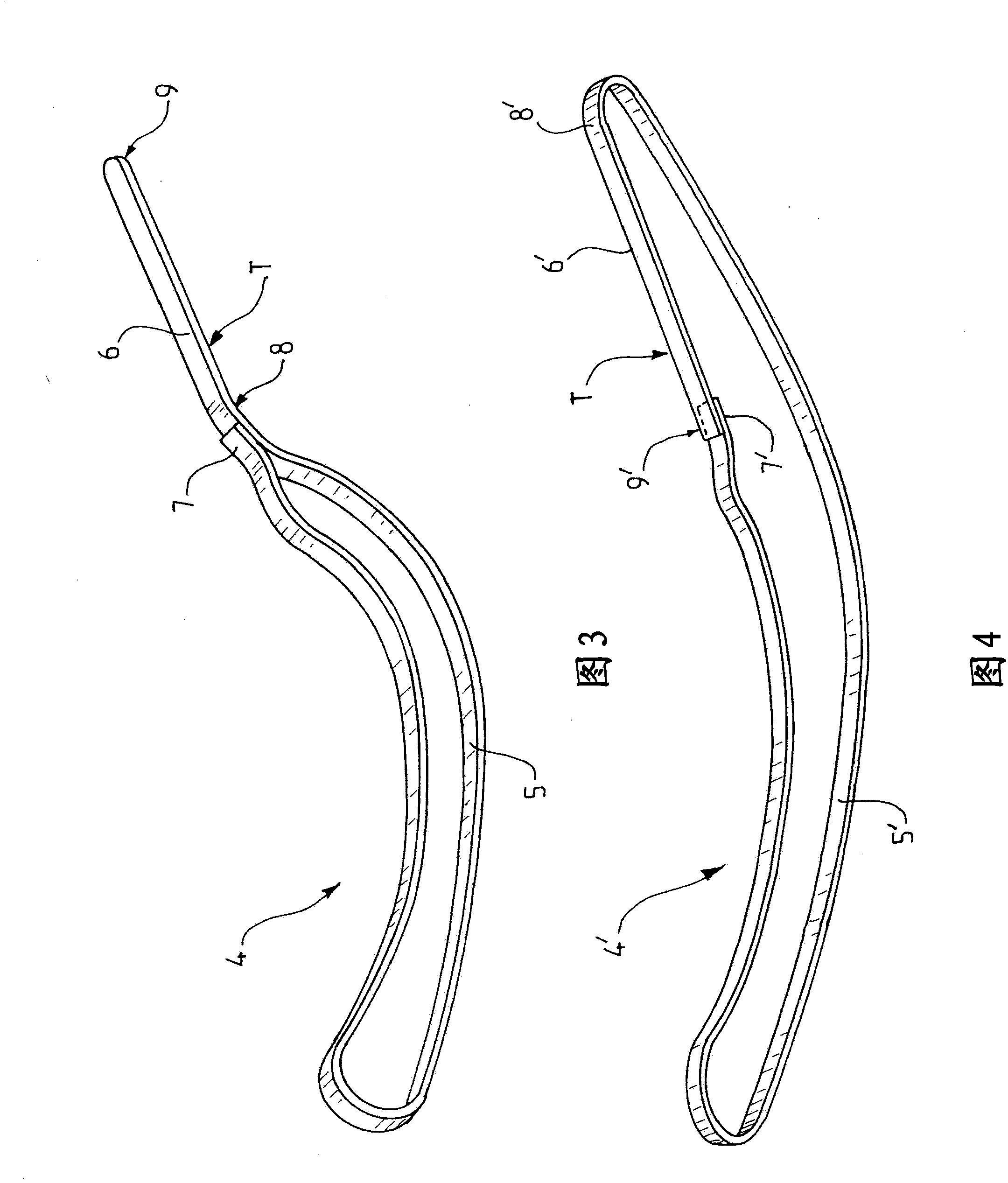
[0050] The device comprises a fixed body 3 for fixing on a rod, and a flexible strip 4 of braided polymer, for example polyester 6 mm wide and 30 cm long.

[0051] The flexible band 4 also forms a double hitch N for fixation on the vertebra V, the two strands B of the double hitch passing from the same side C of the rod 2 into the fixation body 3, and in substantially the same position as the body. The flush exit S is cut off.

[0052] The device also includes an adjustable locking part M that can adjustably lock the flexible belt on the fixed body 3 .

[0053] ref...


PUM


Abstract

The present invention relates to a vertebral fixation device (1) for holding a vertebra (V) on a rod (2), having a body (3) of U-shaped or substantially U-shaped cross section, a flexible band (4, 4') for connecting said vertebra to the fixation body which is provided with slits (17) for passage of the band and of means (M) for adjustably blocking the flexible band against the rod in the fixation body. The flexible band (4, 4') comprises a loop (5, 5') closed on itself and provided with a flexible lamella (6, 6') which is able to form a guide for passage around the vertebra and into the fixation body.

Description

technical field [0001] The present invention relates to a spinal fixation device for holding a vertebra on a rod, said spinal fixation device comprising: a fixation body having a U-shaped or substantially U-shaped body; The fixed body is equipped with a gap for the flexible belt to pass through; and an adjustable locking part that can adjust and lock the flexible belt against a rod in the fixed body. [0002] The invention has a particularly important but not exclusive application in the field of spinal correction of patients with abnormal curvatures. Background technique [0003] In this situation, the vertebrae are not properly aligned one relative to the other with respect to the vertebral axis, there is a dip between the vertebrae. [0004] In some positions, the sides of the vertebrae are thus closer to each other on one side and farther away from each other on the other side. [0005] In order to correct the whole, it is known to reset the sides of the vertebrae on e...

Claims


Application Information

Patent Timeline
IPC IPC(8): A61B17/70A61B17/84
CPCA61B17/842A61B17/7041A61B17/7053A61B17/707A61B17/70A61B17/84
Inventor R·勒库埃迪克C·贝塞尔利
Owner IMPLANET SA
Learn More