
Assembly comprising at least two components that are fixed together

A technology for fixing components and components, applied in the direction of connecting components, threaded fasteners, locking fasteners, etc., can solve the problem of inaccurate alignment of openings, achieve the effect of compensating for manufacturing tolerances and reducing undesired loads

Active Publication Date: 2014-03-19
布罗泽汽车部件制造哈尔施塔特有限公司
View PDF4 Cites 7 Cited by
  • Summary
  • Abstract
  • Description
  • Claims
  • Application Information

AI Technical Summary

Problems solved by technology

[0003] When fixing two components in this way, the problem often arises in practice that undesired stresses and deformations are introduced at least locally into at least one of the two components via the fixing element
[0005] The device described in DE 198 47 268 A1 with a set-back connection section on one of the two components to be connected to each other here also overcomes the clamping to a certain extent, which is achieved by Observation: When a plurality of identical fastening locations with two openings in each case are provided on two components,—depending on manufacturing tolerances—the openings on the two components that are to be formed superimposed on each other are not aligned exactly with one another.

Method used


Image

  • Assembly comprising at least two components that are fixed together
  • Assembly comprising at least two components that are fixed together
  • Assembly comprising at least two components that are fixed together

Examples


Embodiment Construction

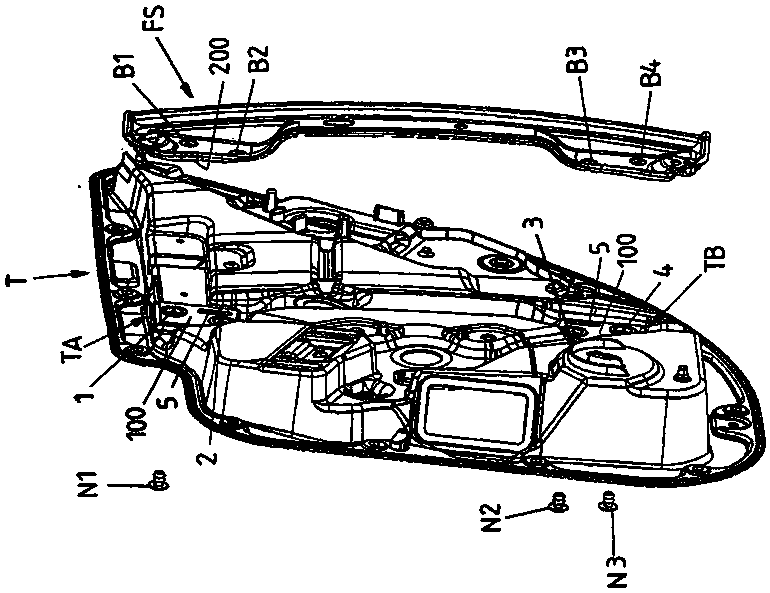
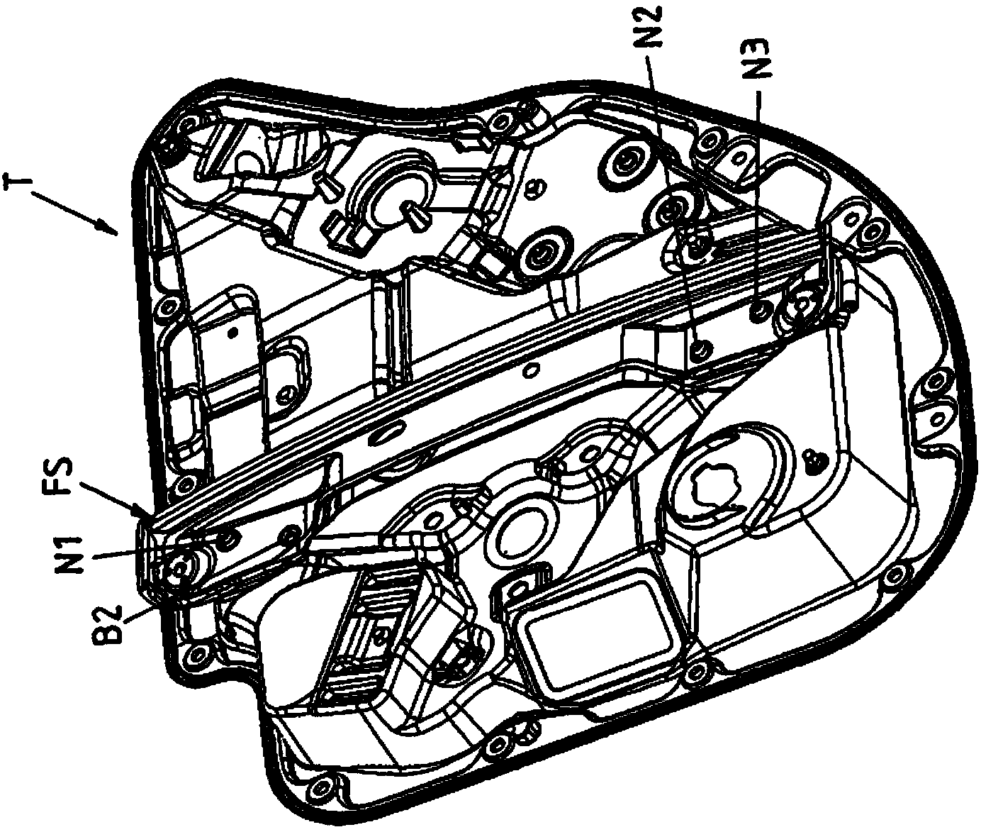
[0051] Figures 1A-1C and 2A-2B show a motor vehicle according to the invention with a first component in the form of a (unit) mount T and a second component in the form of a guide rail FS as part of a motor vehicle window lifter not further shown The first embodiment of the assembly. In this case, the guide rail FS can be fastened in the region of two pairs of fastening points B1, B2 and B3, B4 and thus on the support T at a total of four fastening points, wherein the fastening points B1, B2 and B3, B4 They are spatially separated from each other along the longitudinal extension of the guide rail FS. Thus, one pair of fastening points B1 , B2 is located in the region of the (upper) end of the guide rail FS, while another pair of fastening points B3 , B4 is arranged in the region of the opposite (lower) end of the guide rail FS.

[0052] Protruding sections or protrusions 6.1, 6.2, 6.3 or 6.4 are respectively provided at the fastening points B1 to B4, respectively extending f...


PUM


Abstract

The invention relates to an assembly for a motor vehicle, comprising at least a first component (T, FA, FB) and a second component (FS, G), for example a carrier and a guide rail of a window lifter which are fixed together by means of at least one fastening element, in this case by a plurality of rivets (N1-N4). A fastening element (N1-N4) engages in two openings (72, 82, 92; 62; 62'), of which one opening respectively is formed in a receiving portion (7.1-7.4; 8.3, 8.3*, 8.4; 9.3, 9.4) of the first component (T; FA; FB) and one on a protrusion (6.1-6.4; 6.3', 6.4') of the second component (FS; G), wherein a protrusion (6.1-6.4; 6.3', 6.4') respectively protrudes in an associated receiving portion (7.1-7.4; 8.3, 8.3*, 8.4; 9.3, 9.4) and a flexible or elastic edge section (70, 80, 90) of a receiving portion (7.1, 7.3, 7.4; 8.3, 8.3*, 8.4, 9.3, 9.4) can be shifted in the direction of the associated protrusion (6.1-6.4; 6.3', 6.4'). The at least one edge section (70, 80, 90) that can be shifted in a flexible manner is designed and provided for compensating manufacturing tolerances, such that the two components (T, FS; FA, G; FB, G) automatically align to one another in the area of the flexible edge section (70, 80, 90) during the fastening process and can form a solid connection as intended, wherein the protruding section (6.1-6.4; 6.3', 6.4') is locked in the receiving portion by the edge section (70, 80, 90) which is shifted and pushed against the protruding section (6.1-6.4; 6.3', 6.4').

Description

technical field [0001] The invention relates to an assembly for a motor vehicle having at least one first and a second component according to the preamble of claim 1 and to a device for fastening two components of a motor vehicle assembly to one another. method. Background technique [0002] Fastening elements (for example screws or rivets) are often used to connect the components of a motor vehicle assembly, which clamp the two components together and in which case at least one of the two components passes through (through) the opening. Such fastening elements thus respectively engage into openings on the two components in order to fix the two components in relative position to each other. For example, the first opening on the first component is formed as a through opening and the second opening on the second component is formed as a through opening or a blind hole opening. Here too, the opening on a component can first be formed by providing fastening elements, as is the...

Claims


Application Information

Patent Timeline
IPC IPC(8): F16B5/00B60J5/04F16B39/284
CPCF16B39/284F16B5/0642B60J5/0416B60J5/0468Y10T403/75F16B5/00B60J5/04F16B5/065
Inventor 约阿希姆·卡尔克劳斯·汉佩尔拉尔夫·格斯特劳尔
Owner 布罗泽汽车部件制造哈尔施塔特有限公司
Learn More