Base structure of food material blender

The technology of a mixer and a base is applied in the field of the base structure of the food mixer, and can solve the problems of inconvenient use, too fast and too slow motor rotation speed, etc.

Inactive Publication Date: 2014-03-26
李文钦
View PDF8 Cites 2 Cited by
  • Summary
  • Abstract
  • Description
  • Claims
  • Application Information

AI Technical Summary

Problems solved by technology

[0003] However, the disadvantage of the above-mentioned material blender is that when the user wants to make the rotation speed of the motor faster or slower, he must co

Method used


Image

  • Base structure of food material blender
  • Base structure of food material blender
  • Base structure of food material blender

Examples


Embodiment Construction

[0052] The structure, features and embodiments of the present invention are described below with the aid of the accompanying drawings, so as to enable a better understanding of the present invention.

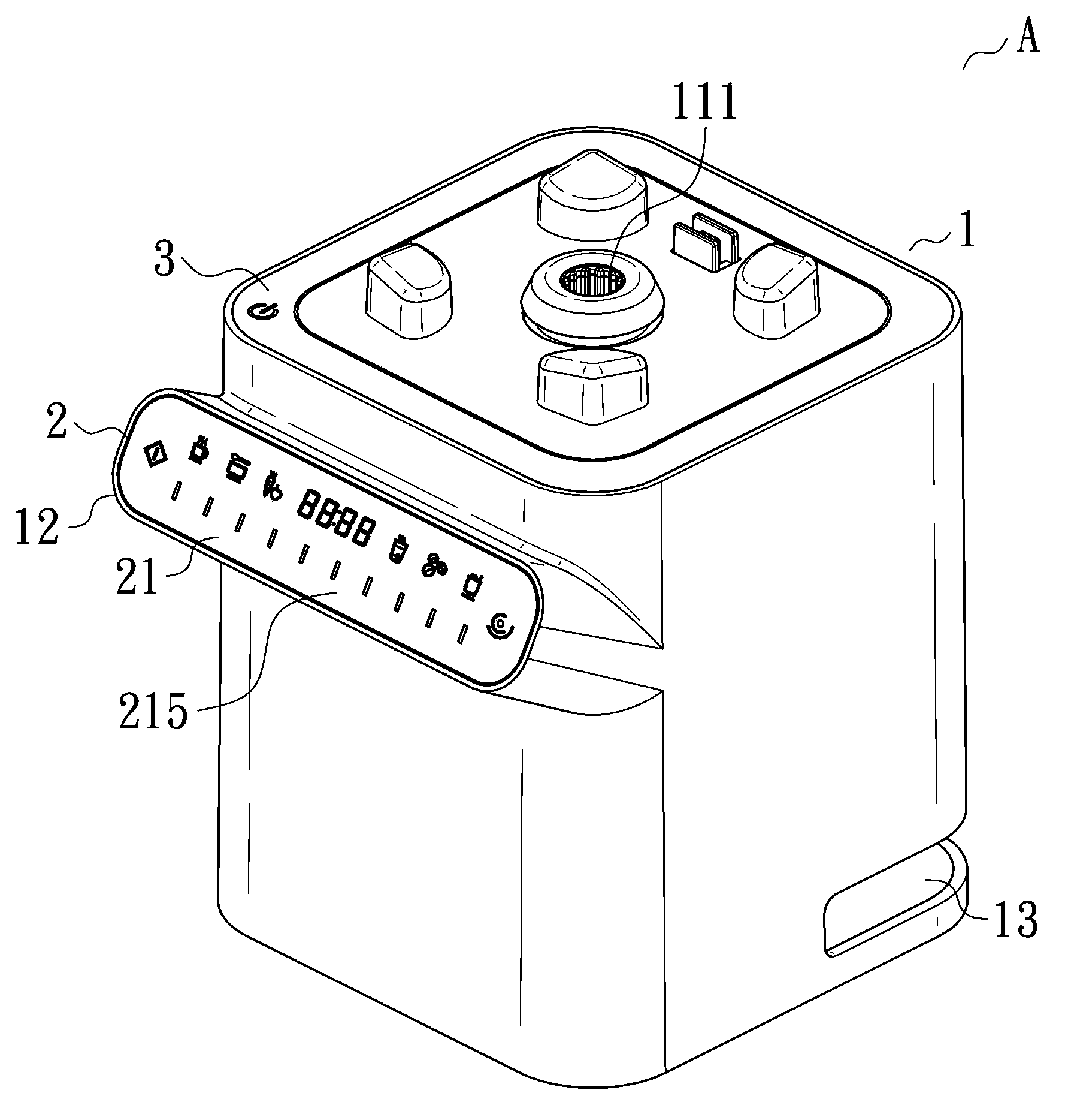
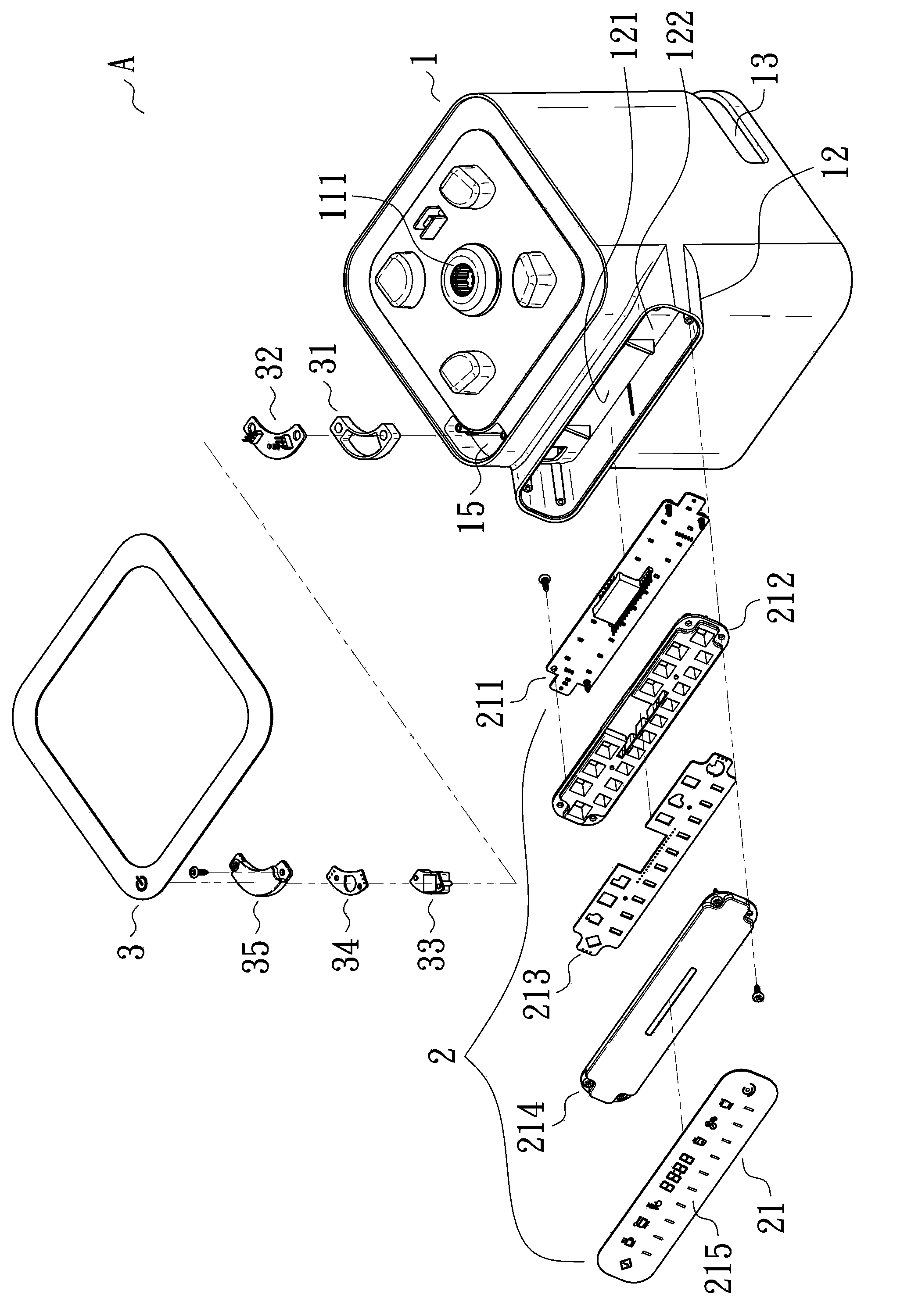
[0053] see figure 1 As shown, the present invention relates to a base structure of a food mixer, and the base A of the food mixer includes:

[0054] A base body 1:

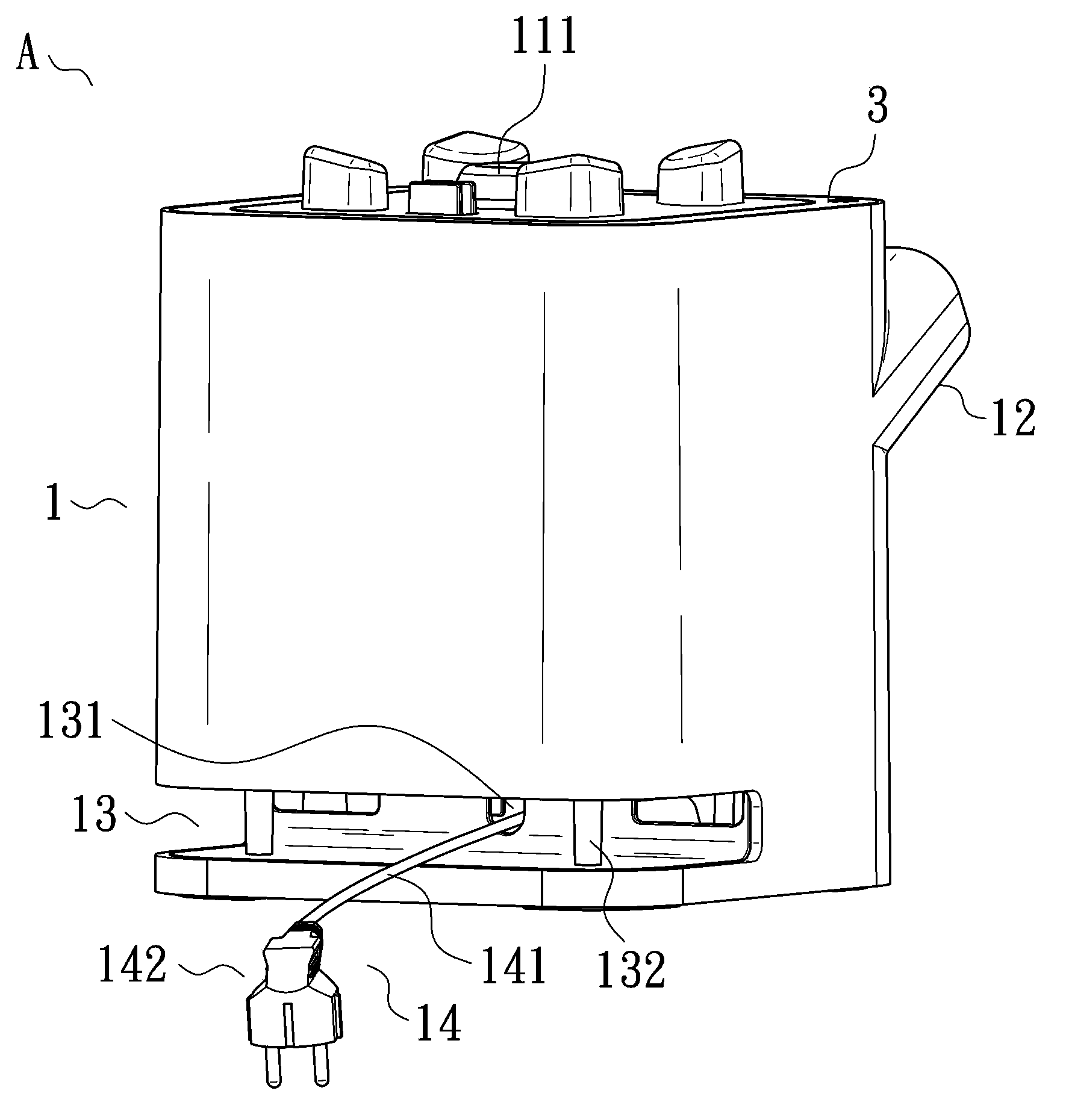
[0055] see figure 1 and cooperate Figure 4 As shown, the base body 1 is provided with a motor 11 inside, the shaft of the motor 11 is connected to a rotating part 111, and the rotating part 111 is exposed on the top surface of the base body 1, and the rotating part 111 can be used with the food mixer. The knives of the cup are connected to form a linkage. Because the cup body of this ingredients blender and its cutting tool do not belong to the scope of protection of the present invention, so in Figure 1 to Figure 4 are not shown in .

[0056] please cooperate figure 2 As shown, the base body 1 is extended...


PUM


Abstract

The invention relates to a base structure of a food material blender. Due to the main fact that one side of a base body extends outwards to form a convex body inclining upwards, a first touch panel is arranged on the surface of the convex body, and a strip-shaped sliding area is arranged on the surface of the first control panel, a user can touch the strip-shaped sliding area with fingers, the fingers can slide left and right, and the user can control the rotation speed of a motor without continuously touching the first touch panel.

Description

technical field [0001] The invention relates to a blender, in particular to a base structure of a food blender. Background technique [0002] A general food mixer includes: a cup with a cutter at the bottom of the cup; a base with a motor connected to the cutter to form a linkage, and a touch panel on the surface of the base that is electrically connected to the motor. The user can control the rotation speed or rotation mode of the motor by touching the touch panel. [0003] However, the disadvantage of the above food mixer is that when the user wants to make the rotation speed of the motor faster or slower, he must continuously touch the touch panel, thus making it easy to damage the motor during operation. The rotation speed is too fast or too slow, thus causing inconvenience in use. Contents of the invention [0004] Based on the deficiencies in the use of the food blender mentioned in the prior art, the purpose of the present invention is to propose a base structure ...

Claims


Application Information

Patent Timeline
IPC IPC(8): A47J43/07
Inventor 李文钦
Owner 李文钦
Why Eureka
Try Eureka