Casting sand mold locking clamp

A technology of locking clamps and turning sand molds, applied in manufacturing tools, casting molding equipment, mold boxes, etc., can solve the problems of insufficient clamping degree of clamping clamps, inability to apply lateral casting, etc., to improve casting quality and simple structure. , the effect of avoiding accidents

Inactive Publication Date: 2014-03-26
戴辉
View PDF10 Cites 4 Cited by
  • Summary
  • Abstract
  • Description
  • Claims
  • Application Information

AI Technical Summary

Problems solved by technology

[0003] The object of the present invention is to provide a casting casting mold locking fixture, which solves the problems of insufficient clamping degree of the clamping fixture for steel ball casting and can not be applied to lateral casting

Method used


Image

  • Casting sand mold locking clamp

Examples


Embodiment Construction

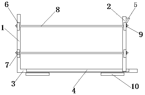
[0012] Examples such as figure 1 As shown, a casting foundry mold locking clamp includes a left clamping block 1, a right clamping block 2 and a locking device arranged between the two clamping blocks. The locking device includes a left clamping block 1, a right clamping The mounting block 6 on the side of the clamp block 2, the double-ended threaded connecting rod 8 penetrating through the through hole 7 of the mounting block 6, and the lock nuts 9 arranged at both ends of the double-ended threaded connecting rod 8, the locking device also includes A base 3 connecting the left clamping block 1 and the right clamping block 2, the left clamping block 1 is arranged on the left end of the base 3, and is integrated with the base 3; the right clamping block 2 is slidably arranged on the upper right part of the base 3 In the chute 4, the upper part of the right clamping block 2 is also provided with a liquid injection funnel 5.

[0013] The lower part of the base 3 is also fixedly ...


PUM


Abstract

The invention provides a casting sand mold locking clamp which comprises a left clamp splice, a right clamp splice and a locking device arranged between the two clamp splices, wherein the locking device comprises a mounting block arranged on the side surfaces of the left clamp splice and right clamp splice, a double thread connecting rod penetrating through a through hole of the mounting block, and locking nuts arranged on both ends of the double thread connecting rod; the locking device also comprises a base for connected with the left clamp splice and right clamp splice; the left clamp splice is arranged on the left end of the base and integrated with the base; and the right clamp splice is arranged in a sliding chute on the right upper part of the base in a sliding mode. The casting sand mold locking clamp can obviously enhance the clamping degree of the mold, improve the casting quality and effectively avoid accidents caused by shedding of the mold set after casting. The upper part of the right clamp splice is provided with a liquid injection hopper capable of implementing lateral casting of the mold set. The casting sand mold locking clamp is simple in structure and easy to implement.

Description

technical field [0001] The invention relates to auxiliary equipment for casting foundry sand molds, in particular to a locking fixture for casting sand foundry molds. Background technique [0002] The steel ball foundry casting clamping fixture is generally composed of a left splint, a right splint, and a locking device. A set of foundry forming molds are clamped in the left splint and right splint, and the locking device is locked, and then molten iron is poured on the horizontal surface of the mold group. . This clamping structure has the defects of insufficient clamping degree, easy confusion of dismounted molds, difficult combination and matching, and inapplicability to lateral casting. Contents of the invention [0003] The purpose of the present invention is to provide a casting sand casting mold locking fixture, which solves the above-mentioned problems of insufficient clamping degree of the clamping fixture for steel ball sand casting and inapplicability to latera...

Claims


Application Information

Patent Timeline
Patent Type & Authority Applications(China)
IPC IPC(8): B22C21/08B22C17/00
Inventor 戴辉
Owner 戴辉
Why Eureka
Try Eureka