
Vertical numerically-controlled milling machine

A CNC milling machine and vertical technology, applied in the field of CNC machine tools, can solve problems such as unfavorable clamping, affecting the translation accuracy of the nut pair, reducing the machining accuracy, etc., to avoid excessive clamping, without frequent cleaning, and improve the machining accuracy.

Inactive Publication Date: 2021-01-15
王素莲
View PDF5 Cites 1 Cited by
  • Summary
  • Abstract
  • Description
  • Claims
  • Application Information

AI Technical Summary

Problems solved by technology

[0003] Most of the chucks used in the existing CNC milling machines are driven by the internal motor to drive the screw to rotate to drive the nut pair to translate, so that the clamp block can be translated to clamp the workpiece to be processed, but the CNC milling machine will produce a lot of debris when processing the workpiece , debris will enter the chuck, so it is necessary to clean the chuck frequently, but the internal structure of the existing chuck is complicated, the loading and unloading is cumbersome, and the movement of the screw rod and the nut pair needs to add lubricating oil regularly, and the lubricating oil is easy Make debris adhere to the screw, which will affect the translation accuracy of the nut pair, which is not conducive to clamping, and will reduce the machining accuracy

Method used


Image

  • Vertical numerically-controlled milling machine
  • Vertical numerically-controlled milling machine
  • Vertical numerically-controlled milling machine

Examples


Embodiment

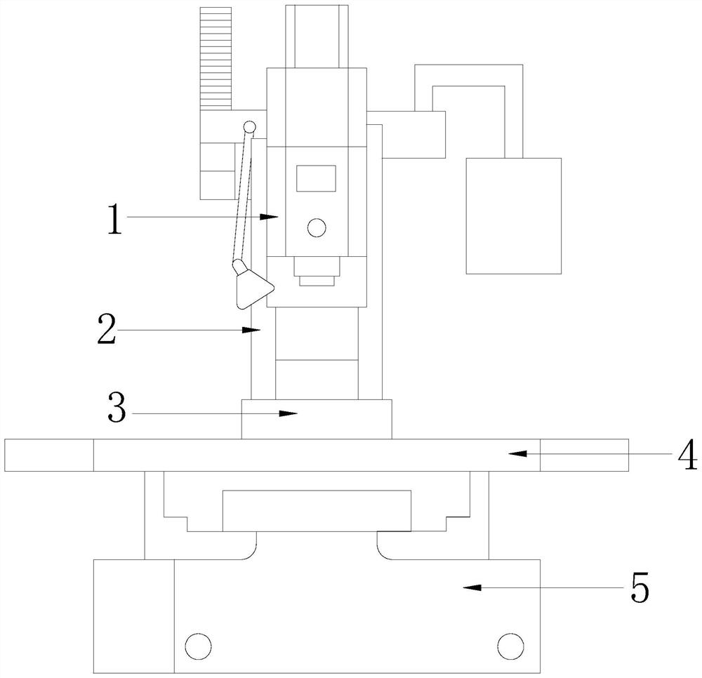
[0029] see Figure 1-7 , The present invention provides a technical scheme of a vertical CNC milling machine: its structure includes a spindle box 1, a body 2, a chuck 3, a worktable 4, and a base 5, the base 5 is fixedly connected with the body 2, and the body 2 A worktable 4 is installed thereon, and the worktable 4 is provided with a chuck 3 , and the chuck 3 is located below the spindle box 1 , and the spindle box 1 is connected to the body 2 .

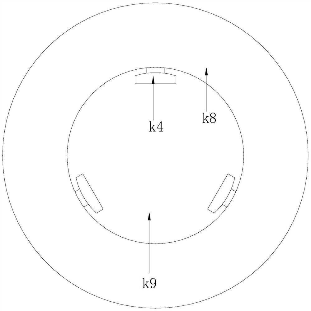
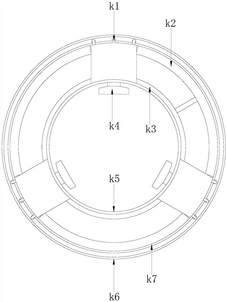
[0030] The chuck 3 includes a liquid storage assembly k1, a pumping ring k2, an inner tube k3, a clamping group k4, an inner ring k5, an outer ring k6, a limit ring k7, a top ring k8, and a bottom plate k9. The bottom plate k9 is connected, the inner ring k5 and the outer ring k6 are fixed on the bottom plate k9, the inner ring k5 and the outer ring k6 are arranged in a concentric structure circle structure, and the tops of the inner ring k5 and the outer ring k6 are connected to the top ring k8, the annular cavity formed between...


PUM


Abstract

The invention discloses a vertical numerically-controlled milling machine. The vertical numerically-controlled milling machine structurally comprises a spindle box, a machine body, a chuck, a workbench and a base, wherein the base is fixedly connected with the machine body; the workbench is installed on the machine body; and the workbench is provided with the chuck. Compared with the prior, the vertical numerically-controlled milling machine has the following beneficial effects: the chuck is simple in structure, air is filled into an inner tube to expand the inner tube, the expansion amount islarge, and different air amounts can be injected according to to-be-machined workpieces of different sizes, so that the chuck can adapt to the to-be-machined workpieces of different specifications; the expanded inner tube can generate a pressure for a liquid storage assembly, the liquid storage assembly can provide a hydraulic pressure for a clamping group, the clamping group can clamp the to-be-machined workpieces, the clamping degree is high, and excessive clamping can be avoided, so that a protection effect is acted on the workpieces; and lubricating oil is not needed, adhesion of chippings can be avoided, frequent cleaning is not needed, and meanwhile increasing for the machining precision is contributed.

Description

technical field [0001] The invention relates to the technical field of numerical control machine tools, in particular to a vertical numerical control milling machine. Background technique [0002] CNC milling machine is a CNC machine tool with the advantages of strong adaptability, high processing accuracy, stable processing quality and high production efficiency. The result is suitable for high-precision machining of mechanical parts. [0003] Most of the chucks used in the existing CNC milling machines are driven by the internal motor to rotate the screw to drive the nut pair to translate, so that the clamping block translates to clamp the workpiece to be processed, but the CNC milling machine will generate a lot of debris when processing the workpiece. , the debris will enter the chuck, so it is necessary to clean the chuck frequently, and the existing chuck has a complex internal structure, complicated loading and unloading, and the movement of the screw and the nut pai...

Claims


Application Information

Patent Timeline
IPC IPC(8): B23C1/06B23C9/00B23Q3/08B23Q11/12
CPCB23C1/06B23C9/00B23Q3/08B23Q11/12
Inventor 王素莲
Owner 王素莲
Learn More