Radiator shutter device

A louver device and radiator technology, which is applied to heat exchanger shells, heat exchange equipment, lighting and heating equipment, etc., can solve the problems of easily damaged rotating blades, unbalanced left and right, and shaft rust, so as to improve the clamping degree , Improve the effect of tension and compression bending stiffness

Active Publication Date: 2010-10-13
BEIJING LONGYUAN COOLING TECH
View PDF6 Cites 1 Cited by
  • Summary
  • Abstract
  • Description
  • Claims
  • Application Information

AI Technical Summary

Problems solved by technology

[0006] 1. The guide rod 104 adopts figure 1 The structure shown has a low degree of clamping with the impeller shaft, and it is made of cast steel. It is easy to rust with the shaft for a long time, and it is not easy to disassemble and maintain
[0007] 2. The pull rod is figure 1 The folded angle steel 102 shown is unbalanced left and right when subjected to tension and pressure, and is prone to eccentricity, and there is a one-sided phenomenon
[0008] 3. figure 1 When the bent plate 101 of the structure shown exceeds a certain length, it is easy to twist and deform and is difficult to control, and there is a phenomenon of turning and scratching the blade rotation
[0009] 4. The impeller shaft 103 is made of ordinary carbon steel, which is easy to rust for a long time and is not easy to disassemble and maintain
[0010] 5. The flange for fixing the impeller shaft 103 is a round copper plate 105. This fixing method is unstable after being stressed, and it is easy to cause circular runout during operation, and copper and iron coexist, which is prone to electrolytic corrosion
[0011] 6. The central axis 106 of the blade is a square steel pipe, and the concentricity of rotation is not easy to control
[0012] 7. The rotating blade 107 is beyond the frame, it is not easy to transport and install, and the rotating blade is easy to be damaged
[0013] The emergence of these defects will easily make the shutters difficult to operate or unable to open and close, and finally affect the normal operation of the entire system

Method used


Image

  • Radiator shutter device
  • Radiator shutter device
  • Radiator shutter device

Examples


Embodiment Construction

[0036] The following examples are used to illustrate the present invention, but are not intended to limit the scope of the present invention.

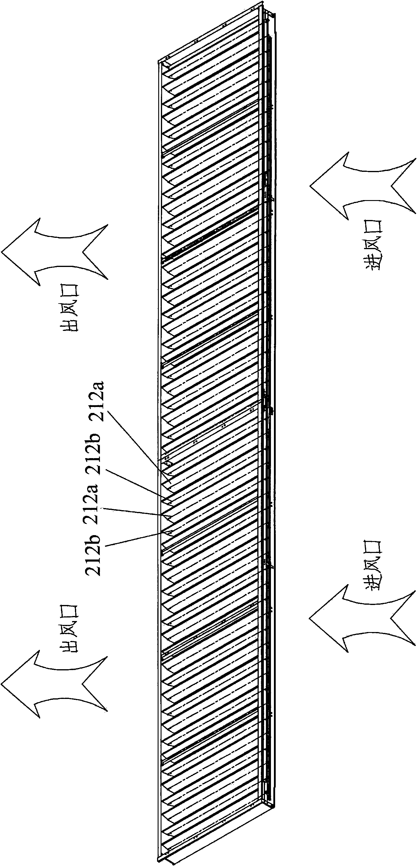
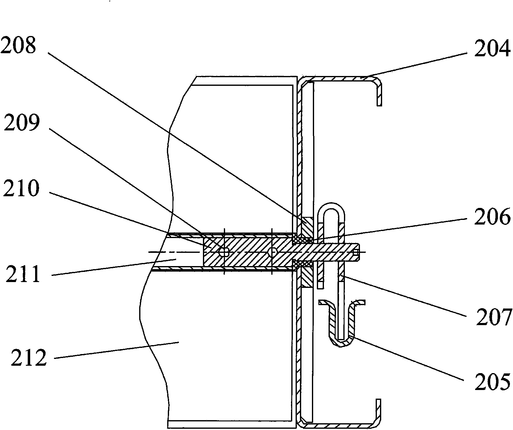
[0037] Such as figure 2 and image 3 As shown, the radiator shutter device of this embodiment includes: a frame 204 , blades 212 , guide rods 207 and pull rods 205 .

[0038] Wherein, the blade 212 has first blades 212 a and second blades 212 b arranged alternately, and all the blades are rotatably arranged on the frame 204 through corresponding blade shafts 210 .

[0039] Guide rod 207 is arranged at one or both ends corresponding to each impeller shaft 210, such as Figure 4 As shown, the guide bar 207 has a first guide bar 207a corresponding to the first vane 212a and a second guide bar 207b corresponding to the second vane 212b.

[0040] Such as Figure 4 As shown, tie rod 205 has a first tie rod 205a connecting all first guide rods 207a and a second tie rod 205b connecting all second guide rods 207b. The first pull rod 205a ...


PUM


Abstract

The invention relates to a radiator shutter device, which comprises a frame, a blade, a guide rod, and a pull rod. The blade is provided with first blades and second blades in alternative arrangement, and all the blades are rotatably arranged on the frame through corresponding blade shafts. The guide rod is arranged at one end or two ends of each blade shaft and is provided with first guide rods and second guide rods which correspond to the first and second blades. The pull rod is provided with a first pull rod which is connected with all the first guide rods and a second pull rod which is connected with all the second guide rods, and the first pull rod and the second pull rod can drive adjacent first and second guide rods to reversely rotate during moving in the same direction. Therefore, the first blades and the second blades relatively rotate. Because the blades adopt the form of opening in opposite directions, the radiator shutter device only regulates the air quantity without changing the wind direction. The pull rod is rolled into U-shaped steel so as to improve the tensile rigidity, and the pull rod is in left and right balance during tension and pressure, and the phenomenon of locking or leaning to one side is absent. The guide rod is made of eta-shaped steel, and the clamping degree is improved.

Description

technical field [0001] The invention relates to the technical field of air cooling, in particular to a radiator shutter device used in an indirect air cooling system of a power station. The device is also suitable for heat exchanger systems in oil refineries and chemical plants. Background technique [0002] The basic application technical scheme of the louvers used in the surface condensing indirect air-cooling heat exchange system of the existing thermal power plant is as follows: [0003] After the exhaust steam of the steam turbine condenses and releases heat, the circulating cooling water enters the multi-group surface air heat exchanger with a large overall size. The heat exchanger uses louvers to adjust the ventilation of the ambient air. The heat of water makes it cool down to the extent that it can continue to absorb the heat released by the condensation of steam turbine exhaust. In this technical process, the louver is one of the key equipments. Its important func...

Claims


Application Information

Patent Timeline
Patent Type & Authority Applications(China)
IPC IPC(8): F28F9/00
Inventor 彭继业王焕忠江洪涛
Owner BEIJING LONGYUAN COOLING TECH
Why Eureka
Try Eureka