Pneumatic chucking tool capable of milling two faces of track link section piece

A chain link, double-sided technology, applied in positioning devices, milling machine equipment, manufacturing tools, etc., can solve the problems of high labor intensity, low production efficiency, quality problems, etc., and achieve power saving, high production efficiency, and work efficiency. quick effect

Inactive Publication Date: 2014-03-26
DALIAN SHENGLONG MACHINERY
View PDF0 Cites 2 Cited by
  • Summary
  • Abstract
  • Description
  • Claims
  • Application Information

AI Technical Summary

Problems solved by technology

When using such tooling, the labor intensity of the workers is high, the production efficiency is low, and the operation is dangerous. Sometimes the workpiece is not clamped tightly, and there will be quality problems. The details are as follows: figure 2 Clamping state shown

Method used


Image

  • Pneumatic chucking tool capable of milling two faces of track link section piece
  • Pneumatic chucking tool capable of milling two faces of track link section piece
  • Pneumatic chucking tool capable of milling two faces of track link section piece

Examples


Embodiment Construction

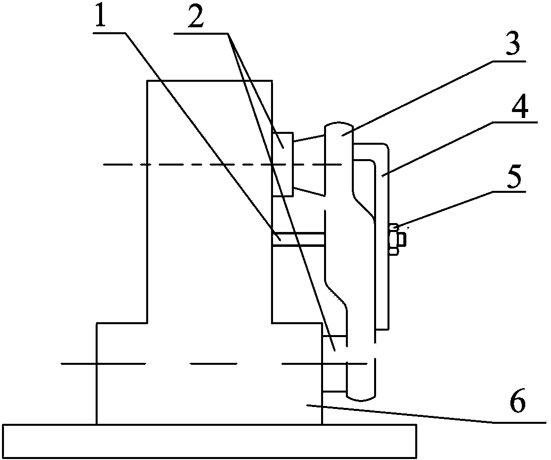
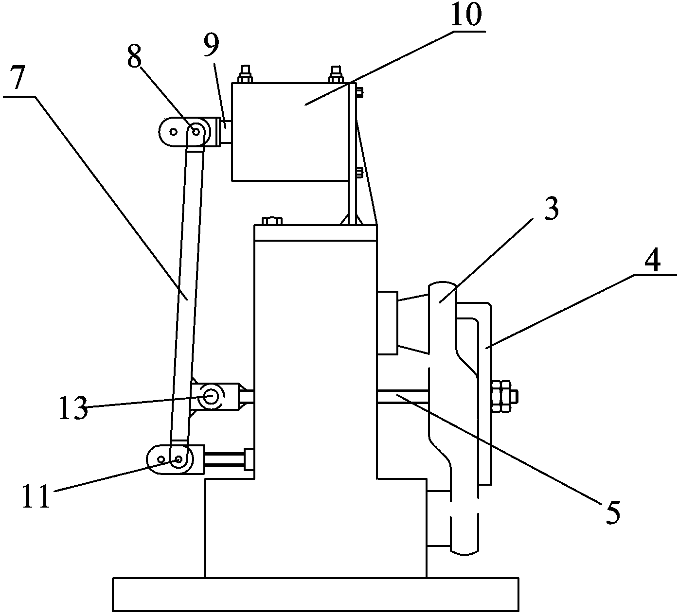
[0017] The present invention studies and updates the existing tooling, develops and designs a set of relatively complete tooling with high efficiency and high yield. Such as image 3 As shown: it includes positioning pins 2 set on the positioning seat 6 at the upper and lower positions, and the screw rod 1 in the middle for piercing the processed chain rail segments. The front end of the screw rod 1 is threaded through the L-shaped pressure plate 4 and then screwed Nut 5. Wherein, the rear end of the screw rod 1 is hingedly connected to the middle part of a lever 7, the lower end of the lever 7 is hingedly connected to the positioning seat 6, and the upper end of the lever 7 is hingedly connected The end of a piston rod 9, the rear part of the piston rod 9 is a telescopic unit. In a preferred manner, the telescopic unit is an air cylinder 10 or a hydraulic cylinder. In the figure, the number 8 is the upper hinge point of the lever 7, the number 11 is the lower hinge point o...


PUM


Abstract

The invention discloses a pneumatic chucking tool capable of milling two faces of a track link section piece. The pneumatic chucking tool comprises positioning pins 2 and a screw 1, wherein the positioning pins 2 are arranged on a positioning base 6 and located at the upper portion of the pneumatic chucking tool and the lower portion of the positioning base 6 respectively, and the screw 1 is arranged in the middle of the positioning base 6 and used for penetrating the track link section piece to be machined. The front end of the screw 1 penetrates through an L-shaped pressing plate 4 and is then connected with a nut 5 in a rotating mode. The rear end of the screw 1 is hinged to the middle of a lever 7. The lower end of the lever 7 is fixedly hinged to the positioning base 6. The upper end of the lever 7 is hinged to one end of a piston rod 9. A telescopic unit is arranged at the rear portion of the piston rod 9. By means of the pneumatic chucking tool, pressing is conducted according to the principle that the lever is pushed through three hinge points and an air cylinder, labor intensity is greatly lowered, and work efficiency is improved by more than one time; meanwhile, electricity is saved for an enterprise, losses are reduced, chucking can be conveniently conducted and is more stable compared with manual chucking, and product quality is guaranteed.

Description

technical field [0001] The present invention relates to a fixture device, more specifically, to a fixture used for milling double sides in chain rail segment processing. Background technique [0002] Crawler-type traveling mechanisms are widely used in construction machinery, and most of them work in harsh environments such as ore mining and construction excavation. Therefore, there are strict requirements for the processing of their parts. [0003] Tracks and chains are an integral part of crawler-type traveling mechanisms such as bulldozers and excavators. However, the most important part of the track and chain is the segment, which plays a vital role in the normal operation of the crawler. However, machining chain rail segments is often difficult. [0004] Such as figure 1 As shown, two surfaces need to be processed to process chain rail segments, that is, two surfaces A and B, but the clamping process is relatively difficult, and workers need to use double-sided milli...

Claims


Application Information

Patent Timeline
Patent Type & Authority Applications(China)
IPC IPC(8): B23Q3/00
CPCB23Q3/082B23C2270/08B23Q3/062
Inventor 蔡万金
Owner DALIAN SHENGLONG MACHINERY
Why Eureka
Try Eureka