
Device for positioning special-shaped components with specific structures

A special-shaped part and a specific technology, applied in the field of machinery, can solve the problems of positioning of special-shaped parts that cannot have a specific structure, and positioning of special-shaped parts that cannot be used, and achieve good positioning effect.

Active Publication Date: 2014-03-26
SICHUAN SHENGONG TUNGSTEN STEEL CUTTING TOOLS
View PDF7 Cites 8 Cited by
  • Summary
  • Abstract
  • Description
  • Claims
  • Application Information

AI Technical Summary

Problems solved by technology

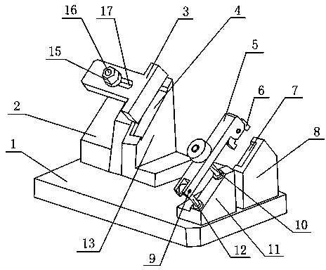
[0004] The purpose of the present invention is to overcome the problem that the above-mentioned existing positioning structure cannot locate special-shaped parts with a specific structure, and a device for positioning special-shaped parts with a specific structure is designed. The device places the workpiece through the concave groove formed by the support plate, and then The pressing device is used for pressing, which solves the problem that the existing positioning structure cannot locate special-shaped parts of a specific structure
Utilize the groove provided on the support plate to snap the special-shaped part into the groove. The size of the end of the special-shaped part matches the size of the groove. Use the positioning parts, and then use the pressing plate and the positioning block to make the positioning of the special-shaped parts stable, and solve the problem that the existing positioning structure cannot locate the special-shaped parts of a specific structure

Method used


Image

  • Device for positioning special-shaped components with specific structures

Examples


Embodiment 1

[0015] Such as figure 1 As shown, the device for positioning special-shaped parts of a specific structure includes a base 1, and the base 1 is provided with a support plate 13 and a support plate 2 8 arranged in parallel to each other, the top surface of the support plate 13 and the support plate 2 8 The top surface is arranged in the same horizontal plane, the top surface of the support plate one 13 is indented to form a groove one 4, the top surface of the support plate two 8 is indented to form a groove two 7, the bottom surface of the groove one 4 and the groove two The bottom surface of 7 is set in the same plane, the side wall of groove one 4 and the corresponding side wall of groove two 7 are set in the same plane, the top of support plate one 13 is provided with pressing plate 3, and one end of pressing plate 3 It is arranged directly above the first groove 4; the positioning block 6 is arranged on the second support plate 8, and the positioning block 6 is arranged dir...


PUM


Abstract

The invention discloses a device for positioning special-shaped components with specific structures. The device comprises a base, wherein a first supporting plate and a second supporting plate which are parallel to each other are arranged on the base; the top of the first supporting plate and the top of the second supporting plate are arranged on the same horizontal plane; the top of the first supporting plate is recessed to form a first groove; the top of the second supporting plate is recessed to form a second groove; the bottom of the first groove and the bottom of the second groove are arranged on the same plane; a side wall of the first groove and a corresponding side wall of the second groove are arranged in the same plane; a pressing plate is arranged above the first supporting plate; one end of the pressing plate is arranged right above the first groove; and a positioning block is arranged on the second supporting plate, and is arranged right above the second groove. Workpieces are placed in the grooves which are formed by recessing the supporting plates, and then are pressed by using a pressing device; the special-shaped components with the specific structures can be positioned; and a positioning effect is high.

Description

technical field [0001] The invention relates to a device for positioning special-shaped parts with a specific structure, which belongs to the field of machinery. Background technique [0002] There are many kinds of mechanical equipment. When the mechanical equipment is running, some of its parts and even itself can perform different forms of mechanical movement. Mechanical equipment consists of driving device, transmission device, transmission device, working device, braking device, protection device, lubrication system, cooling system and other parts. In the processing of mechanical parts, positioning devices are generally provided for positioning and clamping the parts. [0003] The traditional positioning structure cannot locate the special-shaped parts of a specific structure. When positioning the special-shaped parts of a specific structure, a special positioning device needs to be designed. Contents of the invention [0004] The purpose of the present invention is...

Claims


Application Information

Patent Timeline
IPC IPC(8): B23Q3/06
CPCB23Q3/062
Inventor 黄鸿春
Owner SICHUAN SHENGONG TUNGSTEN STEEL CUTTING TOOLS
Learn More