Mould for producing precise plastic parts

A technology of precision plastics and molds, applied in the field of molds for the production of precision plastic parts, can solve the problems of incomplete separation of products and runner plastics, fragile products, low efficiency, etc. The effect of flat cross section

Active Publication Date: 2014-03-26
NINGBO BEILONG PRECISION MOLDING
View PDF2 Cites 1 Cited by
  • Summary
  • Abstract
  • Description
  • Claims
  • Application Information

AI Technical Summary

Problems solved by technology

[0003] The present invention aims to overcome the disadvantages of the precision plastic mold in the prior art that the product and the flow channel plastic cannot be completely separated when the product is released from the mold, and the product is vulnerable, so only pos

Method used


Image

  • Mould for producing precise plastic parts
  • Mould for producing precise plastic parts
  • Mould for producing precise plastic parts

Examples


Embodiment 1

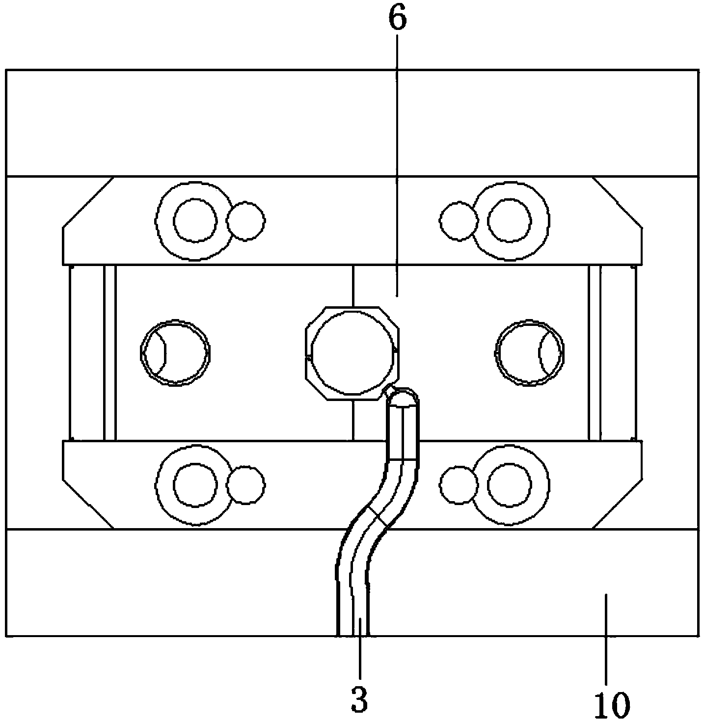
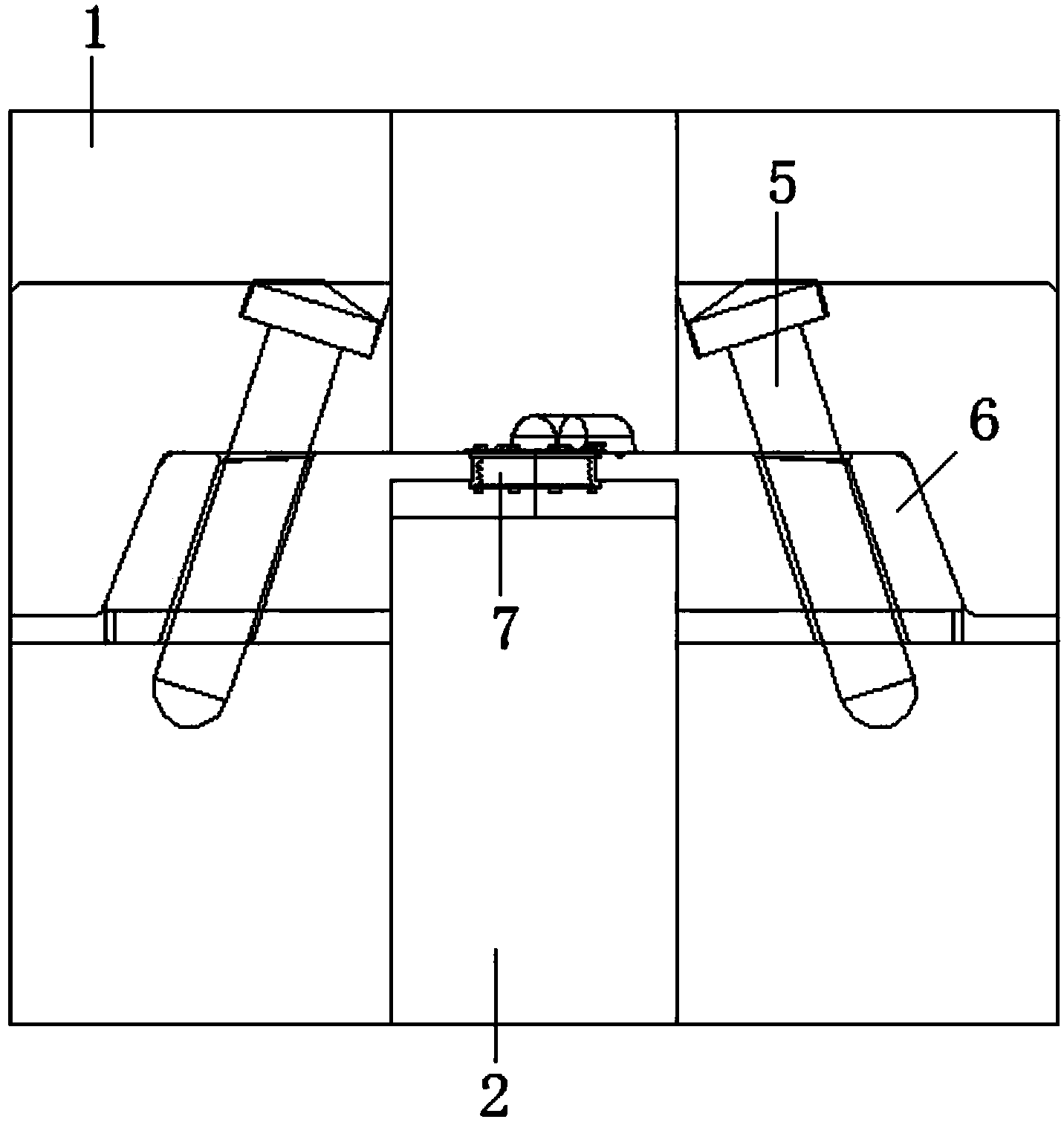
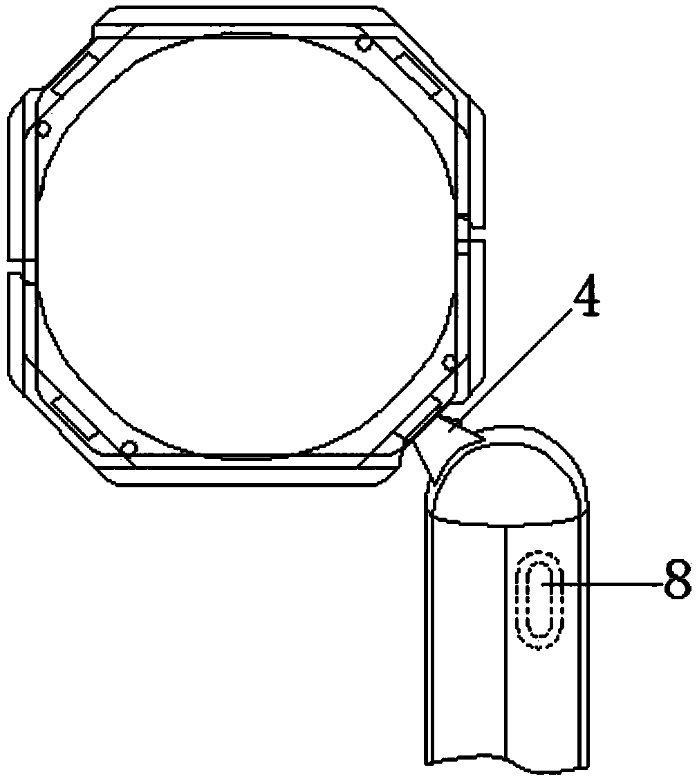
[0019] Embodiment 1: as figure 1 , figure 2 , image 3 , Figure 4 A mold for the production of precision plastic parts is shown, including an upper mold 1, a lower mold 2, and a mold cavity. The mold cavity is communicated with a flow channel 3, and the flow channel 3 is located above the cavity side. The runner 3 includes at least one turning section, and the runner 3 has a submerged section 4 where it contacts the mold cavity, and the uppermost and lowermost upper and lower contours of the submerged section 4 are straight lines, The difference between the angles formed by the upper contour line, the lower contour line and the horizontal plane is greater than 5 degrees, and the described dive section 4 is composed of an upper half and a lower half, and the length of the lower half is at least twice the length of the upper half , the position of the lower half is lower than the main part of the runner 3, and the upper mold 1 is provided with two opposite sliders 6, the sl...

Embodiment 2

[0021] Embodiment 2: as figure 1 , figure 2 , image 3 , Figure 4 , Figure 5 The shown mold for producing precision plastic parts has the same basic structure and implementation as in Example 1, except that the angle formed by the upper contour line and the horizontal plane is larger than that formed by the lower contour line and the horizontal plane. , and the angle difference is 15 to 85 degrees. The upper half includes two upper sides, and the lower half includes two lower sides. The upper side and the lower side are correspondingly overlapped to form two outer sides 9 of the diving section 4, and the two outer sides 9 are For the inclined surface inclined outwardly at the upper part, the distance between the bottoms of the two outer surfaces 9 is the smallest and is consistent with the height of the opening at the end of the flow channel 3 . The opening at the end of the runner 3 is the glue mouth, and the distance between the bottom of the outer surface 9 is the s...


PUM


Abstract

The invention discloses a mould for producing precise plastic parts, and aims to provide a mould, which can automatically separate the product and the plastic in the flow channel during the mould-splitting process, can guarantee the complete and stable separation, and maintains an intact appearance. The mould comprising a upper mould, a lower mould, a mould cavity, and a flow channel; a submergence section is arranged on the joint part between the mould cavity and the flow channel; a upper contour line, which locates in the highest part of the submergence section, and a lower contour line, which locates in the lowest part of the submergence section, are both straight lines, wherein the angle difference between the angle that is formed by the upper contour line and the horizontal plane and the angel that is formed by the lower contour line and the horizontal plane is more than 5 degrees; two opposite slide blocks are arranged in the upper mould, the two slide blocks move in a same straight line but in different directions; two inclined guide pillars, whose upper ends are inward inclined, are arranged in the upper mould, the inclined guide pillars penetrate the upper surfaces and the lower surfaces of the slide blocks; the flow channel is connected to a recessed groove, and the recessed groove is arranged below the flow channel, and communicates with the flow channel. The mould has the advantages that: during a mould splitting process of thin-wall products, automatic separation between the products and the plastic in the flow channel can be successfully achieved, the separation process is rapid and complete, furthermore, the fracture surface is smooth, the products are intact, and the mould splitting process is stable.

Description

technical field [0001] The invention belongs to the field of moulds, in particular to a mold for producing precision plastic parts. Background technique [0002] In the design of many precision plastic parts, especially when it comes to some optical precision plastic parts, due to the complex structure itself, high requirements for size and appearance, and small products, higher requirements are put forward for the manufacture and development of molds, both To be able to guarantee the quality, but also to ensure the daily output. However, a large part of this type of products has an obvious feature that the wall thickness is very thin, and the diameter of the position where the glue is allowed to enter is only about 0.5mm, and some are even below 0.35mm. , such as dispensing ports and conventional latent type ports, there is no way to normally disconnect the product from the runner plastic. The reason is that the product is thin and not strong enough to withstand the tearin...

Claims


Application Information

Patent Timeline
IPC IPC(8): B29C45/26B29C45/38
CPCB29C45/26B29C45/38
Inventor 熊海锦
Owner NINGBO BEILONG PRECISION MOLDING
Why Eureka
Try Eureka