Forecasting and correcting method for joining main deceleration stage and approaching stage

A technology of predictive correction and approach section, which is applied in the direction of extraterrestrial vehicles, aerospace vehicle guidance devices, etc., can solve the difficulty of direct connection of the main deceleration section, the adaptive correction guidance method without the connection function, and the lack of consideration of the connection of attitude, etc. question

Active Publication Date: 2014-03-26
BEIJING INST OF CONTROL ENG
View PDF4 Cites 13 Cited by
  • Summary
  • Abstract
  • Description
  • Claims
  • Application Information

AI Technical Summary

Problems solved by technology

[0003] The Luna and Surveyor series lunar probes respectively adopt the nominal trajectory and gravity turn guidance; the Apollo main deceleration section and the approach section both use quartic polynomial guidance, and optimize the design parameters on the ground to meet the convergence of the thrust change process, but for the attitude Convergence is not considered; the U.S. return to the moon plan proposes to use PEG guidance in the main deceleration section and polynomial guidance in the approach section. The transition from the main deceleration to the approach section is realized through rapid attitude adjustment, and adaptive correction guidance with a connect

Method used


Image

  • Forecasting and correcting method for joining main deceleration stage and approaching stage
  • Forecasting and correcting method for joining main deceleration stage and approaching stage
  • Forecasting and correcting method for joining main deceleration stage and approaching stage

Examples


Embodiment Construction

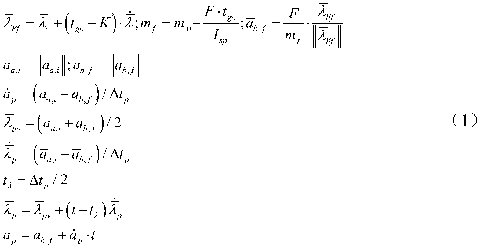
[0041] Such as figure 1 Shown, the present invention is concretely realized as follows:

[0042] (1) Calculate the guidance parameters of the main deceleration section

[0043] Using the current state of the detector and parameters such as the specific impulse and thrust of the main engine, the guidance parameters are calculated. The main deceleration guidance law adopts the PEG guidance law (see the article Space Shuttle Ascent Guidance, Navigation, and Control. The Journal of the Astronautical Science, Vol.XXVII, No.1, pp1-38, January-March, 1979 for details), and the specific calculation The process is briefly described as follows.

[0044] 1) Determine the reference speed increment direction in, and Main deceleration guidance speed target and detector current speed respectively;

[0045] 2) Define the guidance parameters m 0 is the current detector quality, I sp and F are the specific impulse and thrust of the engine respectively, and the remaining main decele...


PUM


Abstract

The invention relates to a forecasting and correcting method for joining a main deceleration stage and an approaching stage. The forecasting and correcting method includes the steps of calculating main deceleration stage guidance parameters, conducting rapid adjustment stage terminal forecasting based on the main deceleration stage guidance parameters and current states of a detector, correcting a main deceleration stage guidance target based on approaching stage inlet conditions, judging whether main deceleration switching conditions are met or not, switching into rapid adjustment guidance if the approaching stage switching conditions are met, otherwise, executing the first step, the second step and the third step again until the main deceleration switching conditions are met, determining rapid adjustment stage guidance parameters according to switching time states, determining current guidance commands according to the rapid adjustment stage guidance parameters, planning approaching stage inlet guidance commands according to the current state, and when an included angle of rapid adjustment stage current guidance commands and the approaching stage inlet guidance commands is smaller than a set value, or the guidance time is completed, switching into approaching stage guidance. According to the forecasting and correcting method, requirements of an approaching stage inlet for gestures, heights, speeds and accelerated speeds are met, and the requirement of the detector for transiting from the main deceleration stage to the approaching stage is met.

Description

technical field [0001] The invention relates to a prediction and correction method connecting the main deceleration and the approaching section, which is mainly applied to deep space landing probes and belongs to the technical field of spacecraft guidance, navigation and control. It can be applied to deep-space celestial body exploration missions such as the moon, Mars, and asteroids, and has extensive application value and market prospects. Background technique [0002] The dynamic descent process of a deep-space celestial body’s soft landing can generally be divided into six task sections: (1) The main deceleration section: the height from the surface of the celestial body is from about 15km to about 3km. The speed reaches the preset value, and the altitude drops to about 3km. (2) Rapid adjustment section: The height from the surface of the celestial body is from about 3km to about 2.4km. The main task of this section is to quickly connect the main deceleration and the ap...

Claims


Application Information

Patent Timeline
IPC IPC(8): B64G1/24B64G1/16
Inventor 黄翔宇张洪华关轶峰李骥梁俊程铭赵宇于萍何健王大轶张晓文
Owner BEIJING INST OF CONTROL ENG
Why Eureka
Try Eureka