
Oil cylinder

An oil cylinder and oil tank technology, which is applied in the hydraulic field, can solve the problems of shortening the effective working stroke of the cylinder, decreasing the working efficiency of the cylinder, and long buffer stroke of the cylinder piston 2, so as to achieve the effect of improving the effective working stroke, improving the working efficiency and optimizing the stability.

Active Publication Date: 2014-03-26
ZOOMLION HEAVY IND CO LTD
View PDF5 Cites 4 Cited by
  • Summary
  • Abstract
  • Description
  • Claims
  • Application Information

AI Technical Summary

Problems solved by technology

As a result, when the oil inlet pressure of the hydraulic oil is small, the buffer stroke of the cylinder piston 2 is too long, which in turn causes the effective working stroke of the oil cylinder to be relatively shortened, and the working efficiency of the oil cylinder decreases
In addition, when the moving speed of the cylinder piston 2 changes and the buffer stroke of the cylinder piston 2 is constant, the expansion and contraction of the cylinder piston rod 9 is unstable.
In other words, under different displacements and gear positions of the pump truck, the expansion and contraction of the cylinder piston rod 9 is not stable enough

Method used


Image

  • Oil cylinder
  • Oil cylinder
  • Oil cylinder

Examples


Embodiment Construction

[0043] Specific embodiments of the present invention will be described in detail below in conjunction with the accompanying drawings. It should be understood that the specific embodiments described here are only used to illustrate and explain the present invention, and are not intended to limit the present invention.

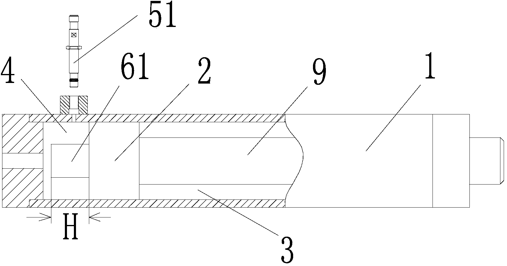
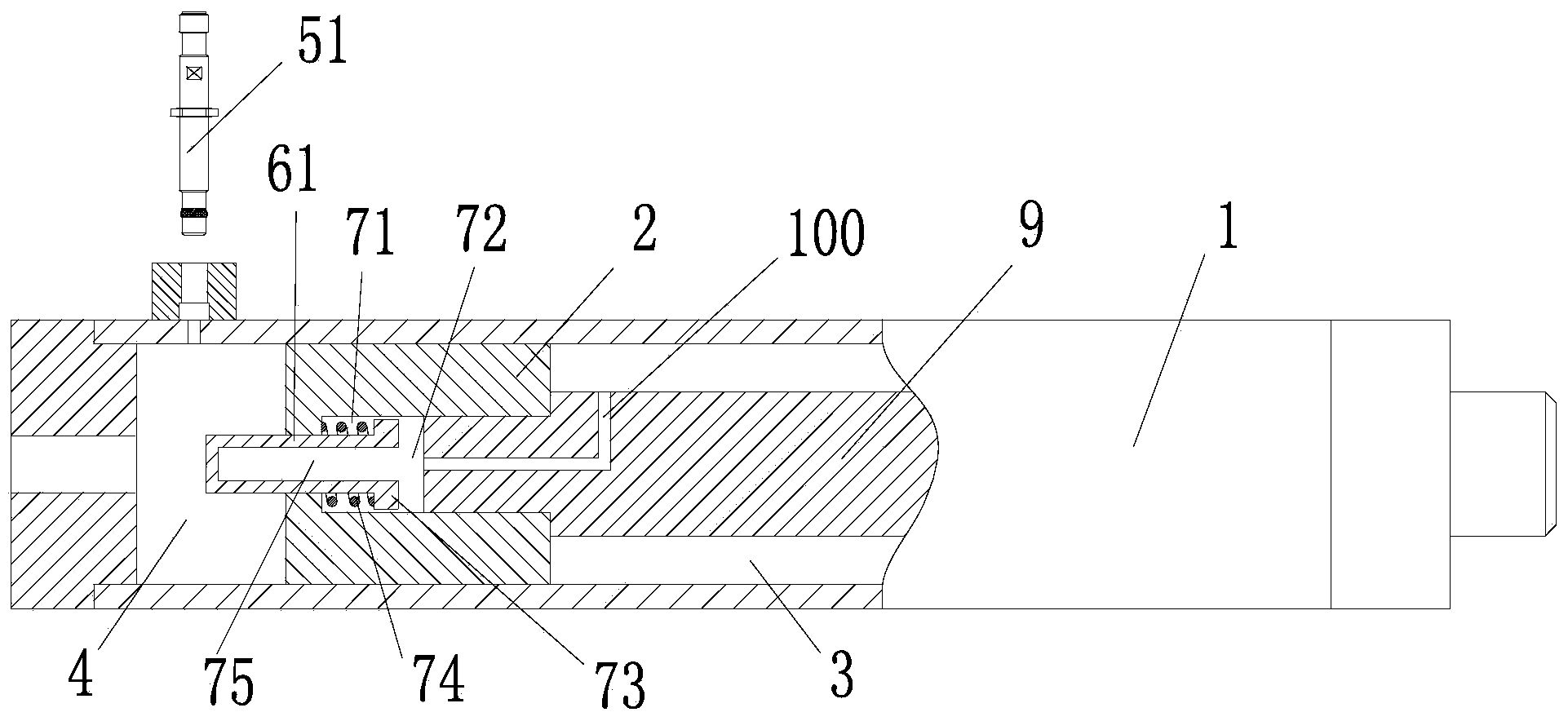
[0044] refer to figure 2 and Figure 4 , the invention provides an oil cylinder. Wherein, a proximity switch is installed on the cylinder barrel 1 of the oil cylinder, and an induction sleeve is installed on the piston 2 of the oil cylinder. The induction sleeve is used to indicate the position of the cylinder piston 2. The proximity switch is used to detect the position change of the induction sleeve and then the position change of the cylinder piston 2, and the proximity switch sends a pumping reversing signal to the system in response to the position change of the induction sleeve.

[0045] Further, according to an embodiment of the present invention, as...


PUM


Abstract

The invention discloses an oil cylinder which comprises an induction sleeve and a proximity switch. The induction sleeve is installed on an oil cylinder piston (2) so as to indicate the position of the oil cylinder piston, and the proximity switch is arranged at the end of an oil cylinder barrel (1) to detect changes of the position of the induction sleeve so as to send out a pumping reversing signal. When oil is fed in an oil cylinder rod cavity (3), the induction sleeve faces an oil cylinder rodless cavity (4) and protrudes out of the oil cylinder piston; or when oil is fed in the oil cylinder rodless cavity, the induction sleeve faces the oil cylinder rod cavity and protrudes out of the oil cylinder piston. The protrusion height (H) of the induction sleeve protruding out of the oil cylinder piston and the oil feeding pressure of hydraulic oil are in the same variation trend. According to the oil cylinder, the effective working stroke can be improved, the working efficiency of the oil cylinder is improved, and the telescopic amount of an oil cylinder piston rod can have the enough stability under different discharging capacities and gears of a pump truck.

Description

technical field [0001] The invention relates to the hydraulic field, in particular to an oil cylinder. Background technique [0002] In order to enable the piston rod of the oil cylinder to expand and contract and keep the piston from touching the end surfaces on both sides of the cylinder barrel, it is necessary to make the hydraulic oil alternate between the rod chamber and the rodless chamber of the oil cylinder and change direction accurately. In order to achieve accurate reversing of the hydraulic oil inlet, it is necessary to detect the position change of the piston in the cylinder in real time. That is, when it is detected that the piston moves close to the end face of the cylinder, the system can change the oil inlet and return direction through the reversing device, so that the piston can realize reverse steering in the buffer stroke section, thereby preventing the piston from touching the end face of the cylinder. [0003] Based on the above purpose, in the prior ...

Claims


Application Information

Patent Timeline
Patent Type & Authority Applications(China)
IPC IPC(8): F15B15/14F15B15/20F15B15/22
Inventor 张海陈晓亮
Owner ZOOMLION HEAVY IND CO LTD
Learn More