Inflatable butterfly valve

An inflatable butterfly valve technology, applied in the field of valves in the chemical industry, can solve the problems affecting the sealing performance of butterfly valves, medium explosion, high wear of sealing structure and valve body, and achieve easy maintenance and maintenance, improved service life, and flexible rotation Effect

Inactive Publication Date: 2014-03-26
HANGZHOU JUNXIONG MACHINERY MFG
View PDF6 Cites 13 Cited by
  • Summary
  • Abstract
  • Description
  • Claims
  • Application Information

AI Technical Summary

Problems solved by technology

[0002] The particularity of the working environment of the pneumatic conveying system determines that the valves used with it must meet the requirements of its working conditions. Butterfly valves are often used to cut off the conveying medium. For butterfly valves with rubber sealing structures, the operation is more inconvenient due to the large torque. In addition, the long-term friction between the sealing structure and the valve body is relatively high, which affects the sealing performance of the butterfly valve and thus affects the work of the entire conveying system.
[0003] For the chemical industry, the butterfly plate is prone to friction during the opening and closing process and is likely to cause safety accidents, such as the explosion of the medium in the conveying system, which is quite dangerous.

Method used


Image

  • Inflatable butterfly valve
  • Inflatable butterfly valve
  • Inflatable butterfly valve

Examples


Embodiment Construction

[0036] In order to make the technical means, creative features, goals and effects achieved by the present invention easy to understand, the present invention will be further described below in conjunction with specific illustrations.

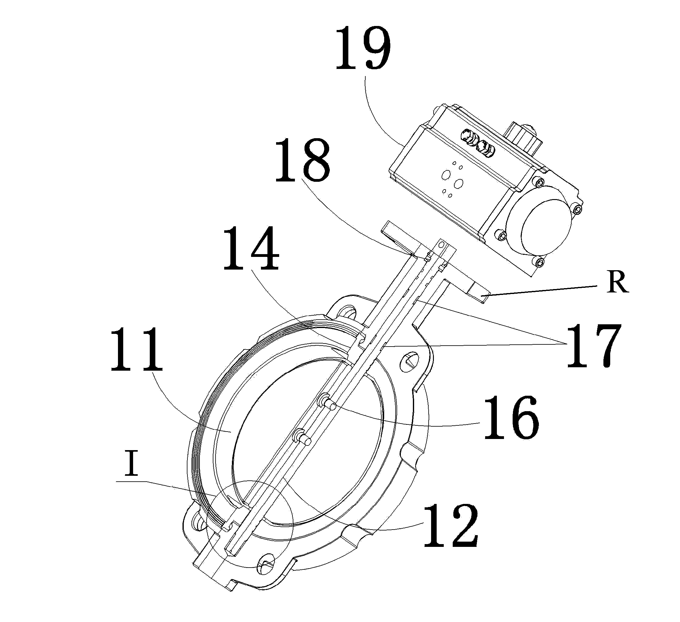
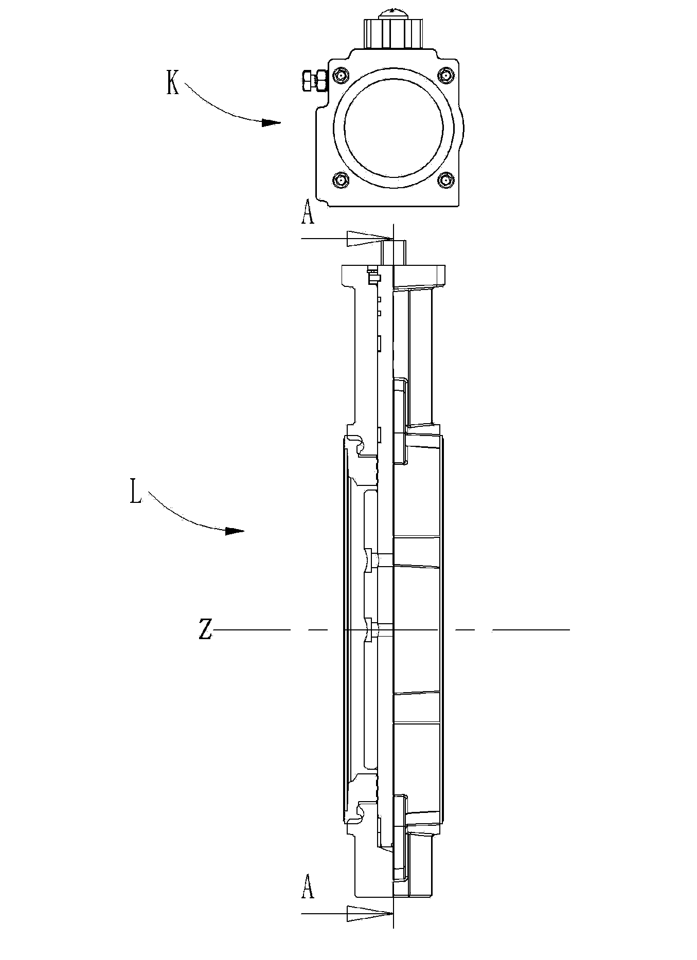
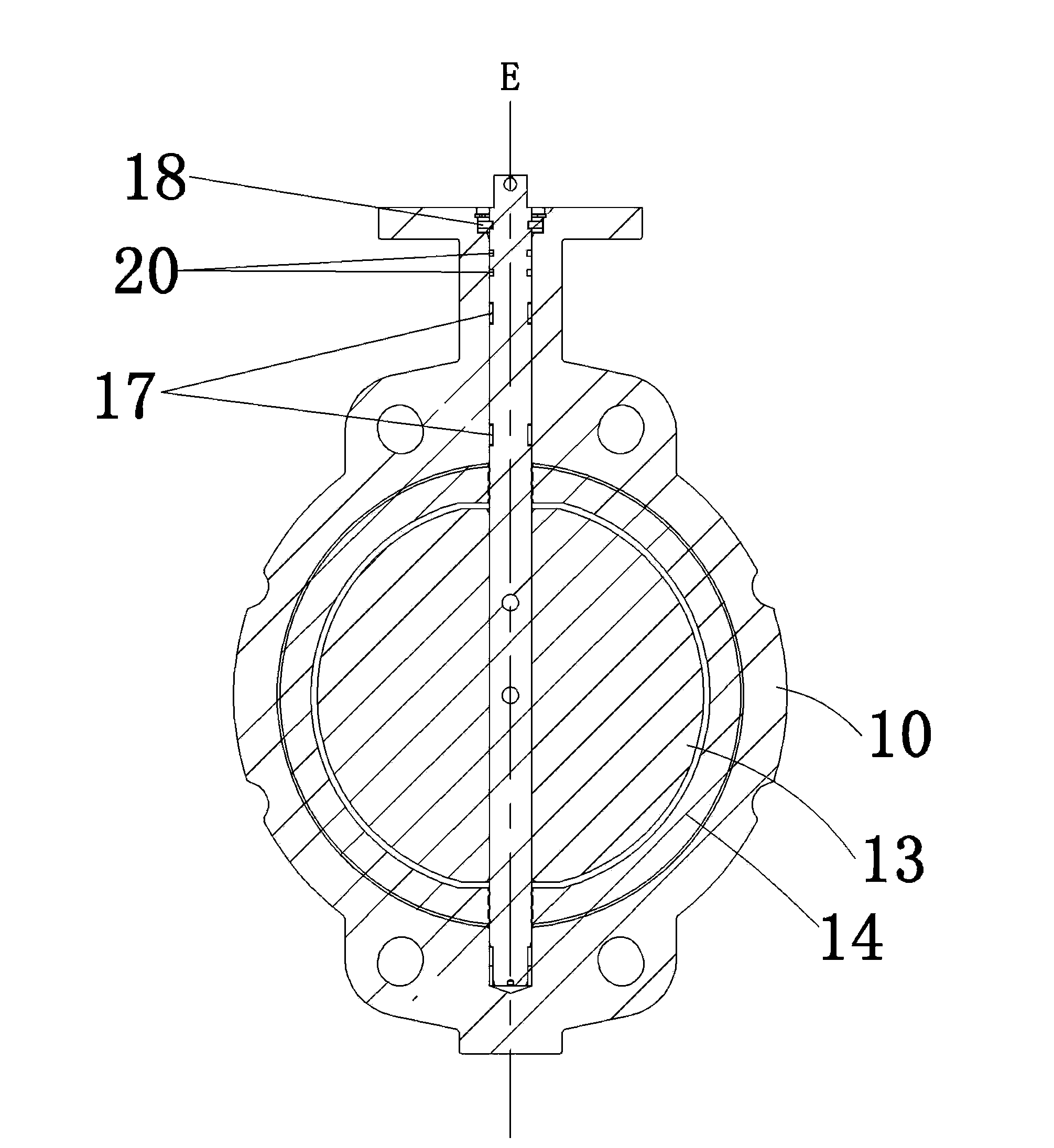
[0037] like Figure 1~4 As shown, an inflatable butterfly valve includes a valve body part L composed of a valve seat 10, a valve shaft 12, and a butterfly plate part, and a control mechanism K that cooperates with the valve body part. The control mechanism K is mainly responsible for controlling the rotation of the valve shaft In order to realize the opening and closing of the butterfly plate part, the control structure K omits part of the structure, which has the function of controlling whether to charge and deflate the embedded body provided in the valve body, so as to facilitate the opening and closing of the butterfly plate part.

[0038] see Figure 1~3 , a valve seat 10 composed of a shell, which has a medium channel 11, the channel has ...


PUM


Abstract

The invention discloses an inflatable butterfly valve. The inflatable butterfly valve is provided with a valve seat, a valve shaft installed on the valve seat and a butterfly plate component. The valve seat is provided with a medium channel provided with a central line in the axial direction of the valve seat. The valve shaft is provided with a rotation axis which extends and passes through the central line. The butterfly plate component is fixed to the valve shaft and arranged inside the medium channel. An extension portion with a valve shaft installation channel arranged internally is arranged above the valve seat. A pneumatic actuator installation flange is arranged at the free end of the extension portion and provided with a pneumatic actuator, and a driving shaft of the pneumatic actuator is connected with the valve shaft. An annular embedding body made of an elastic material is embedded in the inner wall of the valve seat in the circumferential direction and provided with two embedded ends and a deformable portion, the two embedded ends are embedded into the valve seat, the deformable portion is arranged between the embedded ends and forms an inflatable cavity with the inner wall of the valve seat, and the inflatable cavity is communicated with an air inflation hole formed in the valve body. An air inflation hole of the pneumatic actuator and an air inflation hole of the valve body are connected with an external air source through magnetic valves. The inflatable butterfly valve has the advantages of being small in friction and torque, resistant to abrasion, long in service life and suitable for the field of the chemical industry.

Description

technical field [0001] The invention relates to a valve used in the chemical industry, in particular to an inflatable butterfly valve. Background technique [0002] The particularity of the working environment of the pneumatic conveying system determines that the valves used with it must meet the requirements of its working conditions. Butterfly valves are often used to cut off the conveying medium. For butterfly valves with rubber sealing structures, the operation is more inconvenient due to the large torque. Moreover, the long-term friction between the sealing structure and the valve body has a high degree of wear, which affects the sealing performance of the butterfly valve, and then affects the work of the entire delivery system. [0003] For the chemical industry, the butterfly plate is prone to friction during the opening and closing process and is likely to cause safety accidents, such as the explosion of the medium in the conveying system, which is quite dangerous. ...

Claims


Application Information

Patent Timeline
Patent Type & Authority Applications(China)
IPC IPC(8): F16K1/226
CPCF16K1/2263F16K1/224F16K1/2268F16K1/48F16K27/08
Inventor 芦军其应卫龙
Owner HANGZHOU JUNXIONG MACHINERY MFG
Why Eureka
Try Eureka