Gate valve device for ventilating duct

A technology for ventilation pipes and gate valves, which is applied in the direction of valve devices, valve operation/release devices, sliding valves, etc. It can solve the problems of high requirements, inability to achieve the overall sealing of the valve body, and excessive use of space for the gate, to achieve Guaranteed tightness and the effect of solving the problem of space limitation of the valve body

Active Publication Date: 2014-03-26
DIANDUO ELECTROMECHANICAL ENG JIANGSU
View PDF4 Cites 18 Cited by
  • Summary
  • Abstract
  • Description
  • Claims
  • Application Information

AI Technical Summary

Problems solved by technology

[0002] The ventilation pipe gate valve in the prior art is generally composed of a valve body and a gate plate. Depending on the actuator, it can be divided into three type

Method used


Image

  • Gate valve device for ventilating duct
  • Gate valve device for ventilating duct
  • Gate valve device for ventilating duct

Examples


Embodiment Construction

[0033] Hereinafter, in conjunction with the accompanying drawings, a preferred embodiment is described in detail to further illustrate the present invention.

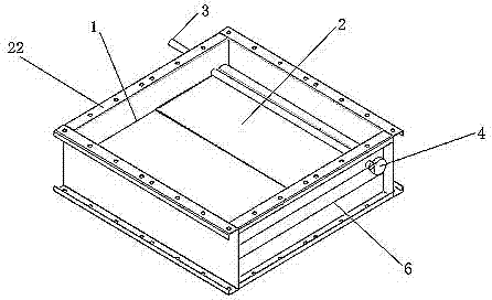
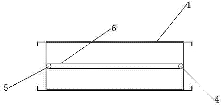
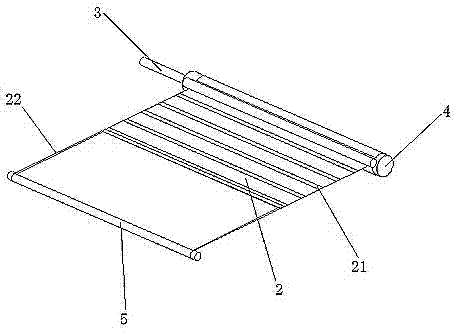
[0034] Such as figure 1 , figure 2 As shown, a gate valve device for a ventilation duct includes a valve body 1; a gate 2 arranged inside the valve body 1; the gate 2 is in a rolling shutter type; an actuator 3 arranged at one end of the valve body 1; and One end of the gate 2 is connected to the driving shaft 4; the driven shaft 5 is connected to the other end of the gate 2 by a rope 22; the actuator 3 and the driving shaft 4 respectively penetrate the side wall of the valve body 1; the driving shaft 4 is connected to the actuator 3; The transmission mechanism 6 connecting the driving shaft 4 and the driven shaft 5; the actuator 3 drives the driving shaft 4 to rotate clockwise or counterclockwise to pull up the gate 2 to achieve opening; the actuator 3 drives the driving shaft 4 to rotate counterclockwise or clockwise thr...


PUM


Abstract

The invention discloses a gate valve device for a ventilating duct. The gate valve device for the ventilating duct comprises a valve body, a gate plate arranged in the valve body in a shutter way, an actuator arranged at one end of the inside of the valve body, a driving shaft connected with one end of the gate plate, a driven shaft connected with the other end of the gate plate through a rope, and a transmission mechanism used for connecting the driving shaft with the driven shaft, wherein the actuator and the driving shaft respectively penetrate through the side wall of the valve body, and the driving shaft is connected with the actuator; the actuator drives the driving shaft to clockwise or counterclockwise rotate to pull the gate plate to be opened, and the actuator drives the driving shaft to counterclockwise or clockwise rotate, and the driven shaft is driven by the transmission mechanism to rotate, so that the gate plate is pulled by the driven shaft through rolling the rope to be closed. The gate plate is embedded in the valve body, and does not interfere with other devices when being opened and closed, so that the valve sealing and space limitation problems are effectively solved.

Description

Technical field [0001] The invention relates to a gate valve in the valve field, in particular to a gate valve device for a ventilation pipe. Background technique [0002] The ventilation pipe gate valve in the prior art is generally composed of a valve body and a gate. Depending on the actuator, it can be divided into three types: manual, electric and pneumatic. However, the main drawback of gate valves is that the gate valve is too large and requires more space. High, and the gate must be drawn out of the valve body when it is opened, and the valve body cannot be sealed as a whole. Summary of the invention [0003] The purpose of the present invention is to provide a gate valve device for ventilation pipes, the gate plate is embedded in the valve body, and it will not interfere with other equipment when it is opened and closed, and effectively solves the problems of sealing and space limitation of the gate valve. [0004] In order to achieve the above objective, the present inven...

Claims


Application Information

Patent Timeline
IPC IPC(8): F16K3/30
CPCF16K3/0245F16K3/314F16K3/3165F16K31/53
Inventor 钟平周益斌
Owner DIANDUO ELECTROMECHANICAL ENG JIANGSU
Why Eureka
Try Eureka