Heat radiator of LED lamp

A technology of LED lamps and radiators, applied in lighting and heating equipment, semiconductor devices of light-emitting elements, cooling/heating devices of lighting devices, etc., can solve the problems of LED lamp base aging and light decay, and achieve good heat dissipation effect, Fast heat dissipation and the effect of expanding the heat dissipation area

Inactive Publication Date: 2014-03-26
长兴恒动光电有限公司
View PDF5 Cites 1 Cited by
  • Summary
  • Abstract
  • Description
  • Claims
  • Application Information

AI Technical Summary

Problems solved by technology

However, there is heat on the back of the LED lamp base, which cannot dissipate the heat quickly, which will easily cause the aging and light decay of the LED lamp base

Method used


Image

  • Heat radiator of LED lamp
  • Heat radiator of LED lamp
  • Heat radiator of LED lamp

Examples


Embodiment Construction

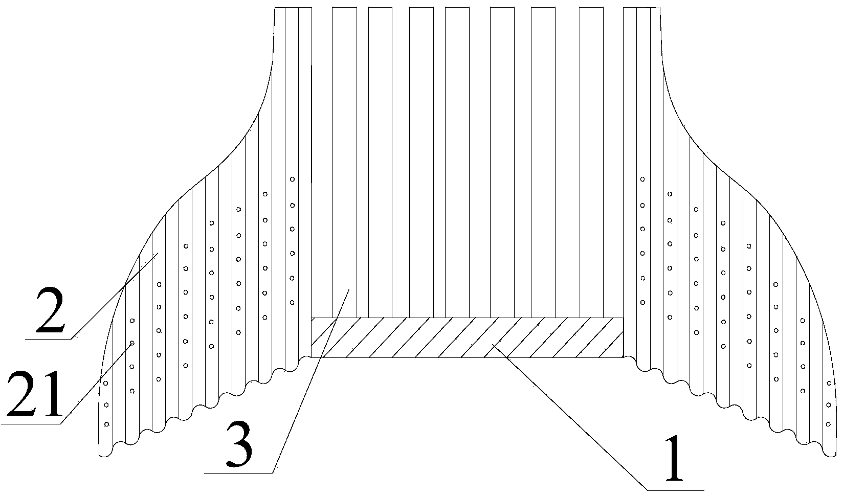
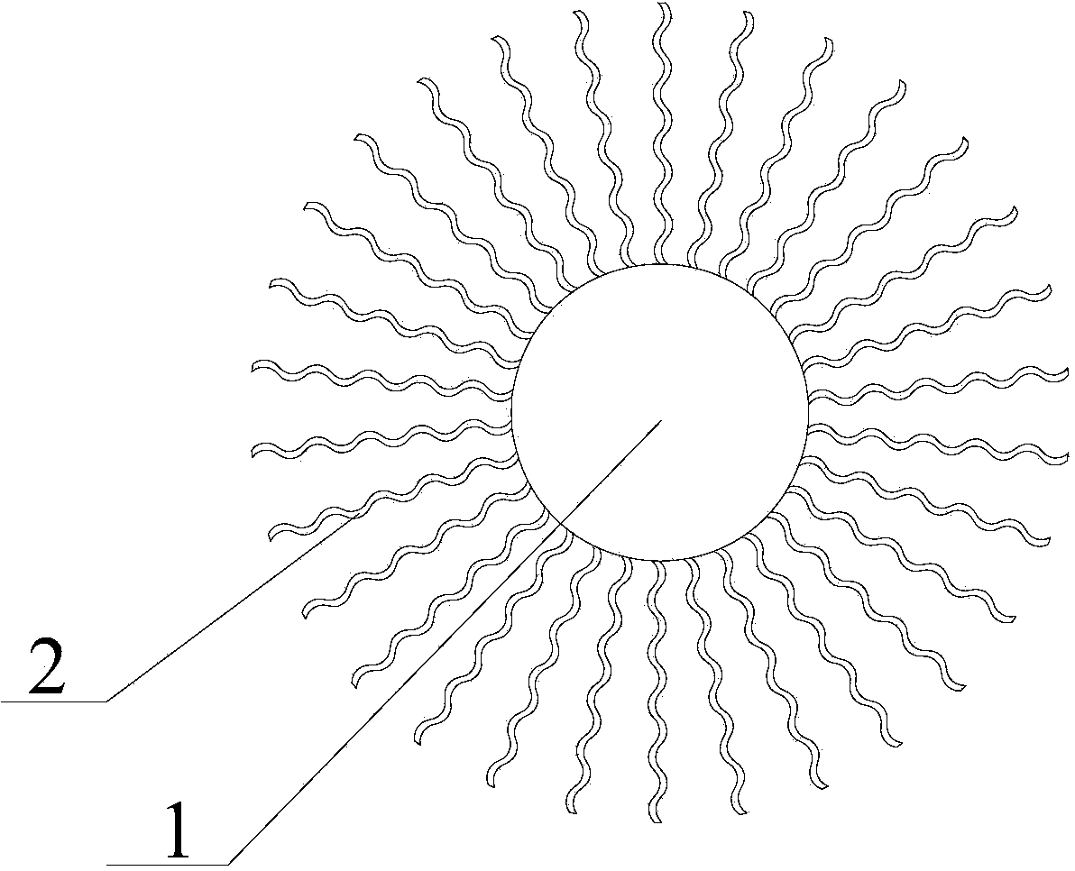
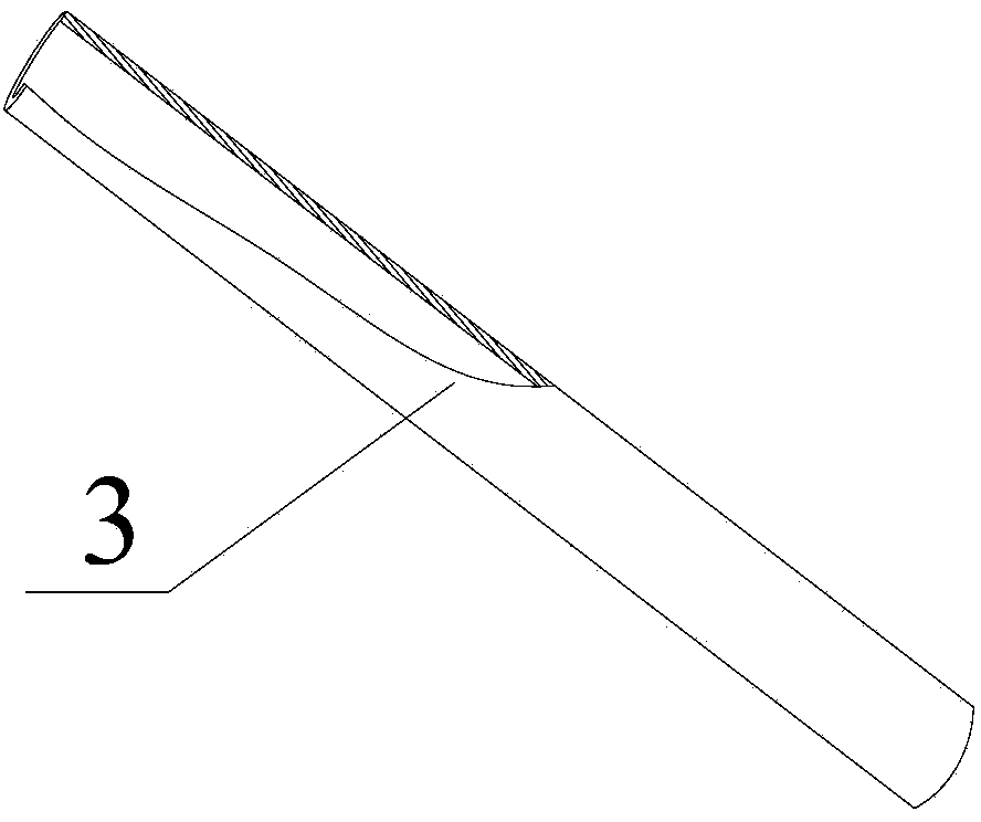
[0018] Such as Figure 1-3 As shown, the LED lamp radiator includes an LED lamp base 1, the lower bottom surface of the LED lamp base 1 is the LED lamp installation surface, and several cooling pipes 3 are arranged on the upper bottom surface of the LED lamp base 1, and the LED lamp base 1 A plurality of cooling fins 2 facing the upper bottom surface of the LED lamp base 1 are connected to the outer peripheral wall of the LED lamp base 1 . Radiating fins 2 are connected to the outer peripheral wall of the LED lamp base 1 for heat dissipation, and a heat dissipation pipe 3 is also arranged on the upper bottom surface of the LED lamp base 1 to increase the heat dissipation area and speed up the heat dissipation. Referring to the partial sectional view of the radiating pipe 3, it can be seen that the internal hollow structure of the radiating pipe 3 increases the heat dissipation area and further accelerates the heat dissipation speed. The LED lamp base 1 described in this embod...


PUM


Abstract

The invention discloses a heat radiator of an LED lamp. The heat radiator comprises an LED lamp base. The lower bottom face of the LED lamp base is an LED lamp mounting face. The upper bottom face of the LED lamp base is provided with a plurality of radiating tubes. The peripheral wall of the LED lamp base is connected with a plurality of radiating fins which are arranged towards the upper bottom face of the LED lamp base. The heat radiator of the LED lamp is high in heat dissipation speed, good in heat dissipation effect and good in luminous effect due to the fact that the illumination area of the bulb-type LED lamp is enlarged.

Description

technical field [0001] The invention relates to a radiator structure for an LED lamp. Background technique [0002] The heat sink of the existing bulb-shaped LED lamp only has fins arranged on the peripheral wall of the LED lamp base for heat dissipation. However, there is heat on the back of the LED lamp base, which cannot dissipate the heat quickly, which may easily cause aging and light decay of the LED lamp base. Contents of the invention [0003] The problem to be solved by the present invention is to provide a heat sink for LED lamps, which has fast heat dissipation speed and good heat dissipation effect, and increases the lighting area of ​​the bulb-shaped LED lamp with good lighting effect. [0004] In order to solve the above-mentioned technical problems, the present invention adopts the following technical scheme: LED lamp radiator, including LED lamp base, the lower bottom surface of the LED lamp base is the LED lamp installation surface, and several cooling ra...

Claims


Application Information

Patent Timeline
Patent Type & Authority Applications(China)
IPC IPC(8): F21V29/00F21Y101/02F21V29/77F21V29/83F21Y115/10
Inventor 罗学民罗红琴吴冰
Owner 长兴恒动光电有限公司
Why Eureka
Try Eureka